Longitudinal calibration method in mounting shaft device

A technology of equipment installation and calibration method, which is applied in the field of longitudinal calibration method, can solve the problems of large installation error, difficult operation, complicated process, etc., and achieve the effects of high installation accuracy, reduced labor intensity, and short installation time

Active Publication Date: 2010-05-12
LINGBAO CITY JINYUAN MINING
View PDF0 Cites 8 Cited by
  • Summary
  • Abstract
  • Description
  • Claims
  • Application Information

AI Technical Summary

Problems solved by technology

[0003] The purpose of the present invention is to provide a new longitudinal calibration method in the installation of shaft equipment, which overcomes the shortcomings of the existing method, such as complicated process, large installation error and difficult operation

Method used


Image

  • Longitudinal calibration method in mounting shaft device
  • Longitudinal calibration method in mounting shaft device
  • Longitudinal calibration method in mounting shaft device

Examples


Embodiment 1

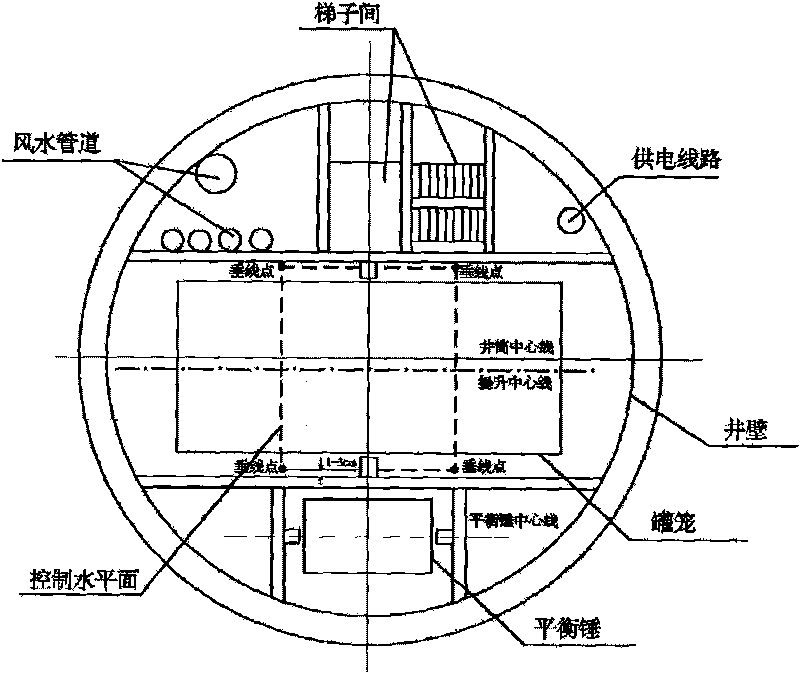
[0030] The shaft is 580 meters long, and the main equipment of the shaft is single cage, counterweight (operating equipment), 7 beams (2 main beams, 5 auxiliary beams), 4 vertical beams, ladder room, wind and water pipes, cables (fixed facilities) . The longitudinal calibration method in the installation of shaft equipment, including the arrangement of the measuring vertical line, the determination of the horizontal installation surface and the setting out of the installation position of the horizontal equipment, wherein:

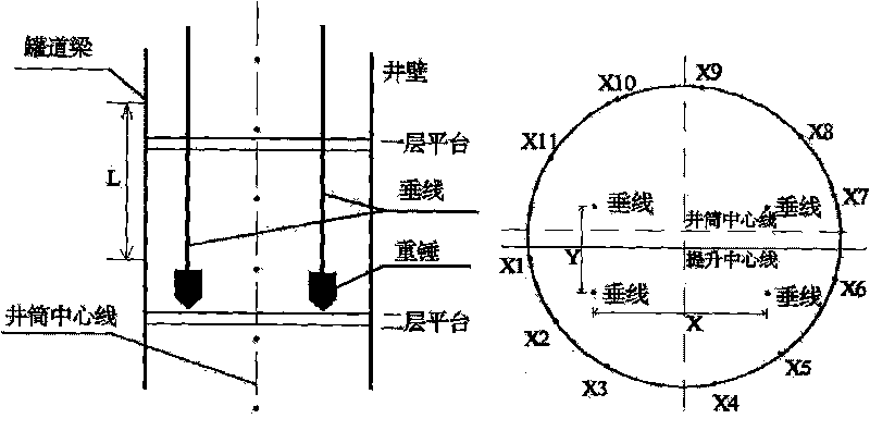
[0031] 1) The layout of the measuring vertical line is as follows: first determine the position of the vertical line: see figure 1 , design 4 parallel vertical lines along the two main beams, the vertical line is located between the two beams, and the vertical distance between the adjacent beams is 3cm; then stake out the vertical lines and wellbore equipment on the temporarily closed well surface sealing plate The plane position and the installation desi...


PUM

PropertyMeasurementUnit
Diameteraaaaaaaaaa

Abstract

The invention belongs to a mine survey staking-out technique, and particularly relates to a longitudinal calibration method in mounting a shaft device. The method comprises the steps: arranging a measurement vertical line, determining a horizontal mounting surface, and staking out a device position on the horizontal mounting surface. The longitudinal calibration method is simple, has strong operability, short mounting time and high mounting accuracy, and reduces the labor intensity.

Description

(1) Technical field [0001] The invention belongs to mine surveying and setting out technology, in particular to a longitudinal calibration method in shaft equipment installation. (2) Background technology [0002] In recent years, prospecting projects have been extended to middle-deep areas, and shaft development has become the main development method of middle-deep ore bodies. The installation accuracy of the shaft equipment directly affects the lifting operation effect. However, the installation technology of the shaft equipment is complicated, the construction is difficult, and there are many equipment installed in the shaft, and the relative position requires high accuracy. A little carelessness will lead to uneven force on the operation of the shaft cage. Large wear and tear, and even safety accidents. Therefore, during the shaft installation process, it is very important to accurately calibrate the design position of the equipment. The traditional method of calibrati...

Claims


Application Information

Patent Timeline
IPC IPC(8): G01C15/02G01C15/10G01C15/14
Inventor 习玉良
Owner LINGBAO CITY JINYUAN MINING
Why Eureka
Try Eureka