
Impulse electromagnet for electromagnetic acoustic transducer

A pulsed electromagnet and electromagnetic ultrasonic technology, applied in the field of pulsed electromagnets, can solve the problems of inconvenience, reduced energy conversion efficiency, wear, etc., and achieve the effects of convenient volume change, low power consumption, and high design flexibility

Inactive Publication Date: 2010-05-12
HARBIN INST OF TECH
View PDF0 Cites 16 Cited by
  • Summary
  • Abstract
  • Description
  • Claims
  • Application Information

AI Technical Summary

Problems solved by technology

Although these magnetic field generation methods can effectively provide the strong magnetic field required for EMAT work, they make the probe bulky, heavy and inconvenient to carry, and there are still many shortcomings: the permanent magnet magnetic field is strong and constant, and in practical applications At the same time, the constant magnetic field is easy to make the probe absorb a large amount of iron filings, which is difficult to clean; when the temperature rises to the Curie point of the ferromagnetic material, the ferromagnetic material becomes paramagnetic, and the permanent magnet and The magnetism of the electromagnet core disappears, so that the static magnetic field required for the transducer to work is significantly weakened, and the energy conversion efficiency is significantly reduced; although DC and power frequency AC electromagnets can turn off the power supply when not in use, such electromagnets are designed Generally, dynamic parameters are not considered, and the magnetic field takes a long time to establish and end. When the frequency of repeated work of the transducer is high, the electromagnet cannot be effectively switched on and off. Generally, the electromagnet needs to be kept energized during the repeated work of the transducer.
[0006] The application of pulsed electromagnets in the field of electromagnetic ultrasound has not yet been reported

Method used


Image

  • Impulse electromagnet for electromagnetic acoustic transducer
  • Impulse electromagnet for electromagnetic acoustic transducer
  • Impulse electromagnet for electromagnetic acoustic transducer

Examples


Embodiment 1

[0018] Embodiment 1, combining figure 1 , the present invention is a kind of pulse electromagnet that is used for electromagnetic ultrasonic transducer, and it is made up of pulse electromagnet (1) and pulse electromagnet driving circuit (4), and pulse electromagnet driving circuit (4) connects pulse electromagnet (1).

[0019] The present invention also has the following technical characteristics:

[0020] The pulse electromagnet (1) includes a skeleton (2) and a coil (3), and the coil (3) is wound on the skeleton (2).

[0021] Described pulse electromagnet drive circuit (4) comprises power pulse shaping circuit (5), power drive circuit (6), control host (7) and booster circuit (8), and control host (7) connects power drive circuit ( 6) and the boost circuit (8), the power drive circuit (6) is connected to the power pulse shaping circuit (5), and the power pulse shaping circuit (5) is connected to the boost circuit (8).

Embodiment 2

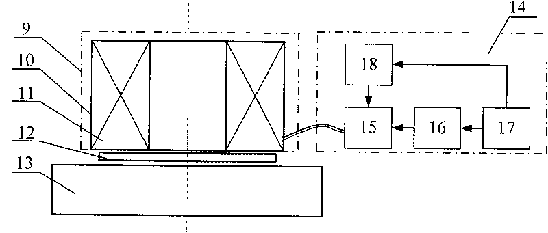
[0022] Example 2, combined with figure 2 , an electromagnetic ultrasonic transducer using a pulsed electromagnet, which is composed of a pulsed electromagnet (9), a pulsed electromagnet drive circuit (14), an electromagnetic ultrasonic coil (12), and a test piece (13). The electromagnetic ultrasonic coil (12) is placed on the test piece (13), the pulse electromagnet (9) is placed on the electromagnetic ultrasonic coil (12), and the pulse electromagnet drive circuit (14) is connected to the pulse electromagnet (9). The pulse electromagnet (9) consists of a skeleton (10) and a coil (11). The coil (11) is wound on the skeleton (10). The pulse electromagnet drive circuit (14) is composed of a power pulse shaping circuit (15), a power drive circuit (16), a control host (17), and a boost circuit (18). Wherein the control host (17) is connected to the power drive circuit (16), the power drive circuit (16) is connected to the power pulse shaping circuit (15), the control host (17) ...

Embodiment 3

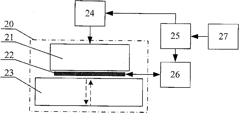
[0024] Example 3, combined with image 3 , Figure 4 , an electromagnetic ultrasonic thickness measuring device using a pulsed electromagnet is an electromagnetic ultrasonic transducer (20) composed of a pulsed electromagnet (21), an electromagnetic ultrasonic coil (22), and a test piece (23), and a pulsed electromagnet drive circuit (24), control circuit (25), transmitting and receiving circuit (26), main frame (27) forms. Figure 4 Among them, the pulse electromagnet coil (28), the electromagnetic ultrasonic coil (29), the eddy current (30), the magnetic force line (31), and the test piece (32). This figure is a schematic diagram of the magnetic field generated by the pulse electromagnet in the non-ferromagnetic material.

[0025] When the device starts to work, the control signal is given by the host to the control circuit, and the control circuit controls the pulse electromagnet drive circuit to generate a large current in the pulse electromagnet coil, which instantly gen...


PUM


Abstract

The invention belongs to the field of electromagnetic ultrasonic nondestructive inspection and discloses an impulse electromagnet for an electromagnetic acoustic transducer, which is capable of improving the performance of the EMAT and reducing the volume and power consumption of the probe of the EMAT. The invention aims to solve various problems aroused by a magnet in the traditional electromagnetic acoustic transducer and reduce probe volume. The impulse electromagnet for the electromagnetic acoustic transducer consists of an impulse electromagnet and an impulse electromagnet driving circuit, wherein the impulse electromagnet consists of a framework and a coil; and the impulse electromagnet driving circuit consists of a power pulse forming circuit, a power driving circuit, a control main machine and a booster circuit. The impulse electromagnet for the electromagnetic acoustic transducer can build a strong magnetic field in a very short period before the EMAT starts to operate to meet the working needs of the EMAT; and after the EMAT stops operating, the magnetic field disappears quickly. The impulse electromagnet is short in operation time, small in power consumption and small in volume and can be used in on-line detection of low-power consumption and portable ferromagnetic test pieces, and the like.

Description

(1) Technical field [0001] The invention relates to electromagnetic ultrasonic detection technology, in particular to a pulsed electromagnet used for electromagnetic ultrasonic transducers. (2) Background technology [0002] Electromagnetic acoustic transducer (EMAT for short) is a new type of ultrasonic transmitting and receiving device. Compared with the traditional piezoelectric ultrasonic transducer, it has the advantages of no acoustic coupling agent and no pretreatment on the surface of the specimen, and has broad application prospects. [0003] EMAT usually consists of three parts: transmitting and receiving coils, strong magnetic field and test pieces. A strong magnetic field is a necessary condition for EMAT to work properly. There are many ways to generate a strong magnetic field, such as permanent magnets, DC electromagnets and power frequency AC electromagnets. Although these magnetic field generation methods can effectively provide the strong magnetic field r...

Claims


Application Information

Patent Timeline
IPC IPC(8): G01B17/02
Inventor 翟国富汪开灿张晓辉刘宝泉蒋韬邱玉王淑娟
Owner HARBIN INST OF TECH
Learn More