Eureka AIR delivers breakthrough ideas for toughest innovation challenges, trusted by R&D personnel around the world.

Valve pile tip structure device of cast-in-place X-shaped concrete pile and using method thereof

A technology of valve pile tips and concrete piles, which is applied in foundation structure engineering, sheet pile walls, buildings, etc., and can solve the problems that prefabricated spud boots cannot be reused, spud boots can only move downwards, and can only move downwards. , to achieve the effect of avoiding heavy manual labor, good integrity and reducing labor costs

Inactive Publication Date: 2010-05-12
HOHAI UNIV +1
View PDF2 Cites 13 Cited by
  • Summary
  • Abstract
  • Description
  • Claims
  • Application Information

AI Technical Summary

Problems solved by technology

The main reason is that the prefabricated spud can and the pile form are not formed as a whole, so it can only move downward, not upward, and when the pile sinks, it will usually cause the spud can to move downward and deviate when it encounters a hard object, or even out of pile formwork
In addition, the prefabricated spud cans cannot be reused. After the piles are formed, the prefabricated spud cans remain permanently in the foundation and cannot be recycled, which wastes materials and costs too much. This is a fatal flaw for construction projects.

Method used


Image

  • Valve pile tip structure device of cast-in-place X-shaped concrete pile and using method thereof
  • Valve pile tip structure device of cast-in-place X-shaped concrete pile and using method thereof
  • Valve pile tip structure device of cast-in-place X-shaped concrete pile and using method thereof

Examples


Embodiment Construction

[0021] Such as figure 1 , 2 , 3, and 4 show:

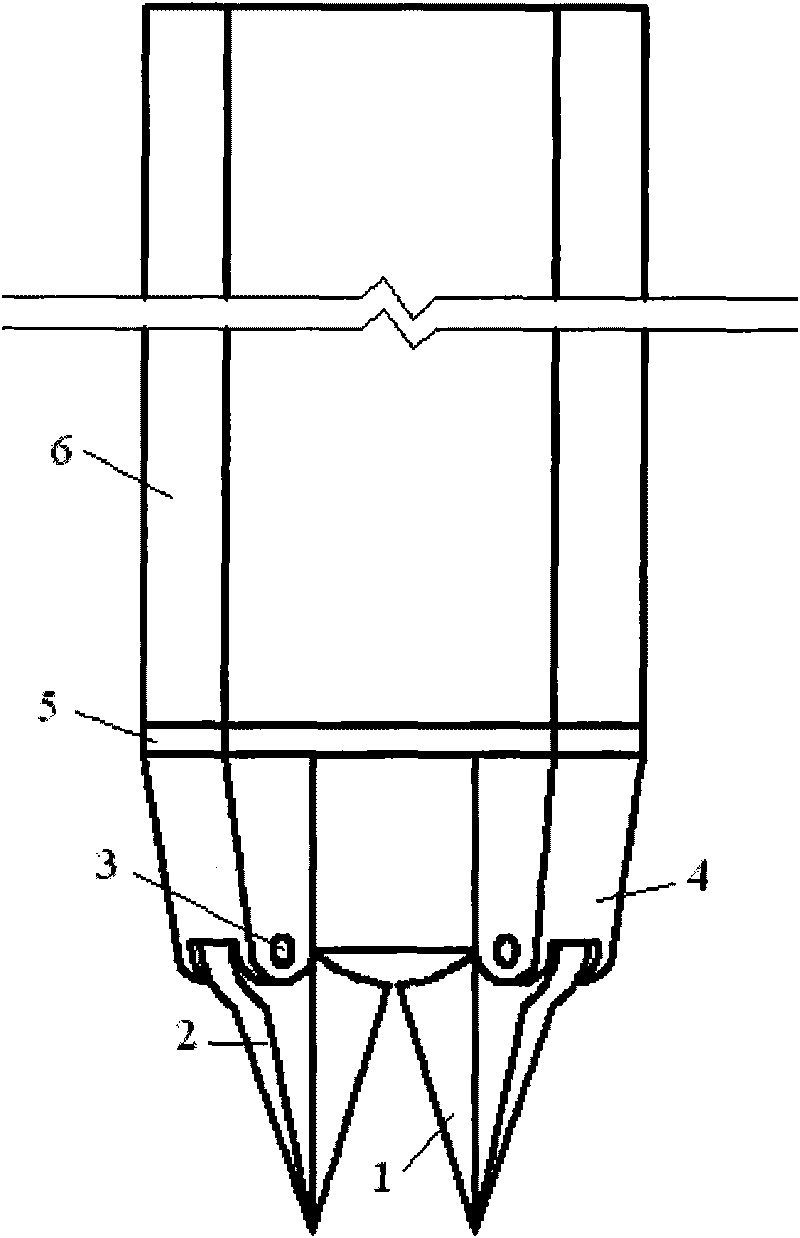
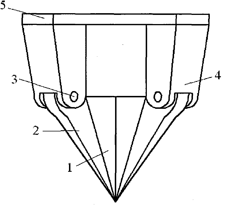
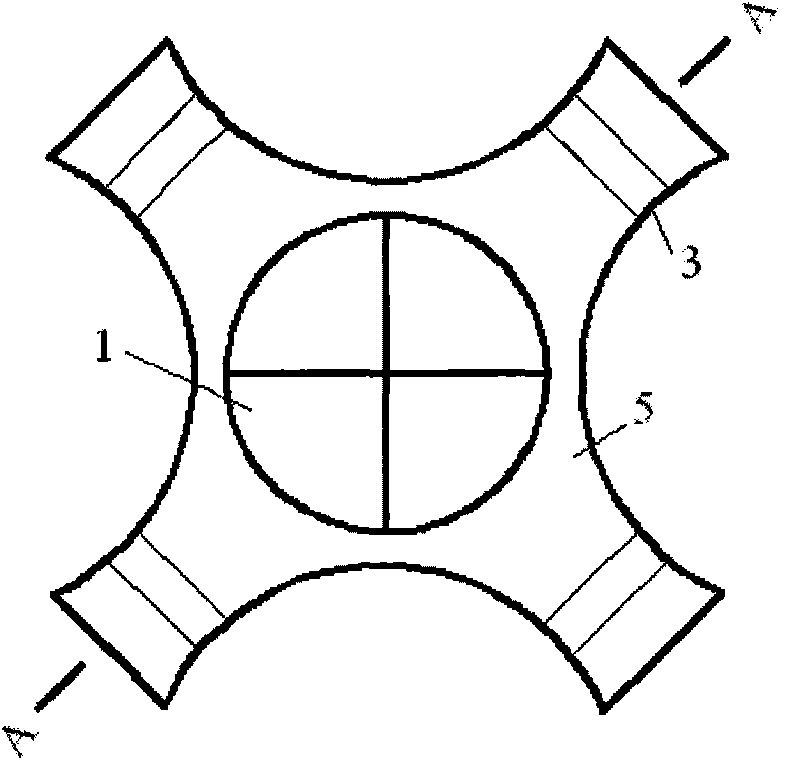
[0022] The lower part of the X-shaped transition section 4 made of steel is hinged with the reinforcement 2 through the connecting hinge 3, and the valve 1 is composed of four curved triangular steel sheets with a large upper part and a smaller lower part; In the middle position of the valve 1, the reinforcement 2 and the valve 1 are fixedly connected as a whole; the connecting hinge 3 flexibly connects the upper ends of each reinforcement 2; when the valve 1 is not closed (such as figure 1 As shown), the four curved triangular steel sheets are separately separated, when closed (such as figure 2 Shown) four curved triangular steel sheets are rotated in the connecting hinge 3 by reinforcing the upper end of the valve 2, and the lower end of the valve 1 pile tip is gathered in the middle, and the whole is shaped like an inverted cone, so that the four curved triangular steel sheets of the valve 1 The lower ends of the pieces wil...


PUM


Abstract

The invention relates to a valve pile tip structure device of a cast-in-place X-shaped concrete pile and a using method thereof. In the valve pile tip structure device, an X-shaped pile die is fixedly connected with a connecting section, the lower end of the connecting section is fixedly connected with a transition section, the lower part of the transition section is rotatablely connected with the upper part of a strengthening rib through a connecting hinge, and the strengthening rib is fixedly connected with a valve; and when the X-shaped pile die is dropped down, the valve pile tip is aligned with a pile position, and a curved surface triangular steel sheet is closed and inserted in a soil body, the X-shaped pile die is vibrated to reach a designed depth so that concrete enters an inner cavity of the valve, and the X-shaped pile die is pulled up to automatically open the curved surface triangular steel sheet so as to form the cast-in-place X-shaped concrete pile. The valve pile tip structure device overcomes the defects that a precast pile shoe is precast in a factory, has long consumed time, large volume and inconvenient transportation, moves and deflects downwards and even breaks away from the pile die, cannot be used repeatedly, has high manufacturing cost, and the like. The valve pile tip structure device avoids repeated physical work, does not need to be precast in the factory, shortens the construction period, and reduces the cost.

Description

technical field [0001] The invention relates to a pile tip structure, in particular to a device and a use method for a cast-in-situ X-shaped concrete pile with a movable flap pile tip structure. Background technique [0002] Before the present invention, there had been a device or method in which the steel casing with the prefabricated reinforced concrete pile shoe was sunk into the soil by hammering pile driving or vibrating pile sinking, and then poured concrete while pulling out the pipe to form a pile. If there are steel bars, hang the steel bar skeleton before pouring concrete. Using hammering pile sinking equipment to sink and pull pipes is called hammer sinking pipe pouring pile; when using vibration exciter to sink and pull pipes, it is called vibration sinking pipe pouring pile. It is also possible to use the vibration-shock double action method to sink the tube. [0003] The cast-in-place X-shaped concrete pile (patent number: 200710020306.3) has a large specific...

Claims


Application Information

Patent Timeline
Patent Type & Authority Applications(China)
IPC IPC(8): E02D5/66E02D11/00
Inventor 刘汉龙王智强丁选明孙俊康雍君
Owner HOHAI UNIV
Why Eureka
Eureka Blog
Learn More