
Numerical control torque synchronous hydraulic bender slide block flexivity compensation mechanism

A slider deflection and compensation mechanism technology, which is applied in the field of hydraulic bending machines, can solve problems such as unsatisfactory bending effects, and achieve the effects of low manufacturing cost and excellent repeat positioning accuracy

Inactive Publication Date: 2010-05-05
朱斌
View PDF6 Cites 14 Cited by
  • Summary
  • Abstract
  • Description
  • Claims
  • Application Information

AI Technical Summary

Problems solved by technology

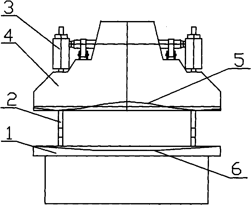
The structure of the current CNC torsion axis synchronous bending machine is as follows: figure 1 As shown, the workbench 1 is fixed on the lower part of the left and right wallboards 2, and the oil cylinder 3 is fixed on the upper part of the left and right wallboards 2. The upper part of the oil cylinder 3 is equipped with a mechanical synchronization mechanism. The piston rod in the oil cylinder 3 is connected with the slider 4. When sheet metal is produced, the slider produces a deflection deformation of the dotted line 5 shown in the figure, and the workbench produces a deflection deformation of the dotted line 6. The slider and the worktable produce a double-concave deflection deformation. The middle angle of the bending workpiece is larger than the two ends, and the bending workpiece is bent. Unsatisfactory bending effect

Method used


Image

  • Numerical control torque synchronous hydraulic bender slide block flexivity compensation mechanism
  • Numerical control torque synchronous hydraulic bender slide block flexivity compensation mechanism
  • Numerical control torque synchronous hydraulic bender slide block flexivity compensation mechanism

Examples


Embodiment Construction

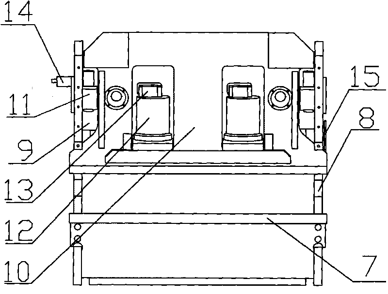
[0012] attached by figure 2 , attached image 3 It can be seen that the slider deflection compensation mechanism of the CNC torsion axis synchronous hydraulic bending machine includes a workbench 7, left and right wall panels 8, front and rear beams 9, sliders 10, left and right stopper seats 11, and left and right oil cylinders 12. The left and right wall panels 8 are located on The side of the bending machine is fastened on the workbench 7. The slider 10 is set in the middle of the front and rear beams 9. The piston rods of the left and right oil cylinders 12 are connected with the slider 10. Two square holes are set on the slider 10. The left and right oil cylinders 12 Place in the square hole and be fixed on the front and rear beams 9. When working, the up and down movement of the slider is driven by the oil cylinder, and the slider works synchronously through the synchronous swing arm. Finally, the slider reaches the bottom dead center, and the slider is pressed on the ...


PUM


Abstract

The invention discloses a numerical control torque synchronous hydraulic bender slide block flexivity compensation mechanism which comprises a workbench (7), a left wallboard and a right wallboard (8), a front beam and a back beam (9), a slide block (10), a left stop dog seat and a right stop dog seat (11), and a left cylinder and a right cylinder (12); the left wallboard and the right wallboard (8) are arranged at the lateral side of the bender and fixed tightly on the workbench (7), the slide block (10) is arranged between the front beam and the back beam (9), the piston rods of the left cylinder and the right cylinder (12) are connected with the slide block (10) which is thereon provided with two square holes, and the piston rods of the left cylinder and the right cylinder (12) are arranged in the square holes and fixed on the front beam and the back beam (9). The invention adopts the above structure, the slide block flexivity of the bender deforms to bulge downwards to form mutual compensation with the dent formed by deforming of the flexivity of the workbench, a flexivity compensation system is adopted to perform numerical control, thus improving working precision of the bender, causing the repeat positioning precision of the slide block of the bender to be superior of that of an electricity-liquid synchronous bender, and reducing manufacturing cost.

Description

technical field [0001] The invention relates to a hydraulic bending machine, in particular to a slider deflection compensation mechanism of a numerically controlled torsion axis synchronous hydraulic bending machine. Background technique [0002] At present, most hydraulic bending machines are controlled by numerical control, and there are two types of numerical control bending machines: numerical control torsion axis synchronous bending machine and numerical control electro-hydraulic synchronous bending machine. CNC torsion shaft synchronous bending machine and CNC electro-hydraulic synchronous bending machine can offset the deflection and deformation of the worktable and slider when working, and obtain a good bending effect. The deflection compensation cylinder is installed on the workbench. This deflection compensation method is expensive and is rarely used in the torsion axis synchronous bending machine. Therefore, when the CNC torsion axis synchronous bending machine be...

Claims


Application Information

Patent Timeline
Patent Type & Authority Applications(China)
IPC IPC(8): B21D11/00B21D5/00
Inventor 朱斌
Owner 朱斌
Learn More