Variable-power running control device for self-propelled harvester
A technology of operation control and harvester, applied in engine control, electrical control, fuel injection control, etc., can solve the problem of high fuel consumption rate, achieve the effect of uniform wear, balanced operation, and easy installation
- Summary
- Abstract
- Description
- Claims
- Application Information
AI Technical Summary
Problems solved by technology
Method used
Image
Examples
Embodiment 1
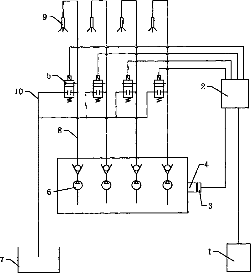
[0023] like figure 1 As shown, the engine of the self-propelled harvester has a mechanical fuel injection system. When the camshaft 4 rotates, each fuel injection pump sub-pump 6 is driven to work. A high-pressure oil pipe 8 is arranged between the fuel injection pump sub-pump 6 and the fuel injection nozzle 9 . Cylinder sensor 3 is installed on the shaft end of camshaft 4 or other parts of the engine, and the installation and position of cylinder sensor 3 are well known to those of ordinary skill in the art, and its function is to detect the cylinder dead center position signal of the engine and rotational speed signals, and deliver these signals to the microprocessor 2. An oil return bypass 10 is provided between the high-pressure oil pipe 8 and the fuel tank 7 of the engine, and an electromagnetic switch valve 5 electrically connected with the microprocessor 2 is provided on the oil return bypass 10; the signal input end of the microprocessor 2 is also connected with the P...
Embodiment 2
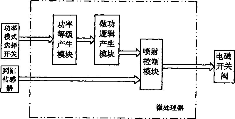
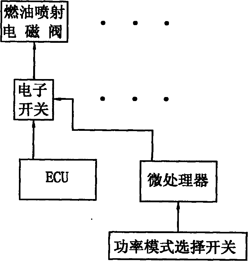
[0030] like image 3 As shown, the engine of the self-propelled harvester has an electronically controlled fuel injection system, and the electronically controlled fuel injection system includes an ECU and a fuel injection solenoid valve controlled by the ECU; the variable power operation control device includes a power mode selector switch for The power mode of the engine is manually selected; the electronic switch, the signal input end of the electronic switch is electrically connected with the ECU, and the signal output end of the electronic switch is electrically connected with the fuel injection solenoid valve; the microprocessor, the The signal input end of the microprocessor is electrically connected to the power mode selection switch, and the signal output end of the microprocessor is electrically connected to the control end of the electronic switch; the specific structure of the microprocessor refers to figure 2 , which includes a power level generating module for g...
Embodiment 3
[0033] It is another embodiment that applies the present invention to an electronically controlled fuel injection system, and its structure is basically the same as that of Embodiment 2, except that it uses the power level generation module and work logic of the microprocessor in Embodiment 2 The generation module and the injection control module are integrated in the ECU, and the electronic switch is omitted, thereby simplifying the circuit structure, which is especially suitable for matching with new models.
[0034] like Figure 4 As shown, the power mode selection switch is electrically connected to the signal input terminal of the ECU; the power level generation module, the work logic generation module and the injection control module are integrated in the ECU, and the injection control module is electrically connected to the fuel injection output module of the ECU , the injection control module outputs a control signal to the fuel injection solenoid valve according to th...
PUM
 Abstract
Description
Claims
Application Information
 - R&D
- Intellectual Property
- Life Sciences
- Materials
- Tech Scout
- Unparalleled Data Quality
- Higher Quality Content
- 60% Fewer Hallucinations
Browse by: Latest US Patents, China's latest patents, Technical Efficacy Thesaurus, Application Domain, Technology Topic, Popular Technical Reports.
© 2025 PatSnap. All rights reserved.Legal|Privacy policy|Modern Slavery Act Transparency Statement|Sitemap|About US| Contact US: help@patsnap.com


