Variable displacement compressor and displacement control system

A capacity control and compressor technology, which is applied in the direction of liquid variable capacity machinery, pump control, mechanical equipment, etc., can solve the problems of the absence of capacity control devices, etc., and achieve the effect of ensuring driving performance

Inactive Publication Date: 2010-03-31
SANDEN CORP
View PDF3 Cites 4 Cited by
  • Summary
  • Abstract
  • Description
  • Claims
  • Application Information

AI Technical Summary

Problems solved by technology

However, there is no capacity control device that can perform the above control

Method used


Image

  • Variable displacement compressor and displacement control system
  • Variable displacement compressor and displacement control system
  • Variable displacement compressor and displacement control system

Examples


Embodiment Construction

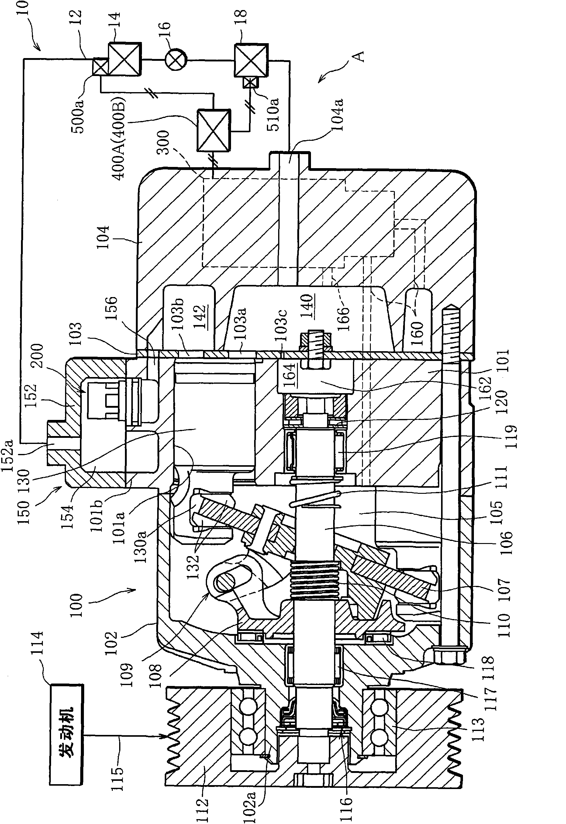
[0081] Hereinafter, the displacement control system A of the variable displacement compressor according to the first embodiment will be described.

[0082] figure 1 A refrigeration cycle 10 of a vehicle air-conditioning system to which the capacity control system A is applied is shown, and the refrigeration cycle 10 includes a circulation path 12 through which a refrigerant as a working fluid circulates. In the circulation path 12, a compressor 100, a heat radiator (condenser) 14, an expander (expansion valve) 16, and an evaporator 18 are interposed sequentially from the flow direction of the refrigerant. If the compressor 100 works, refrigeration The agent circulates in the circulation path 12. That is, the compressor 100 performs a series of steps including a suction process of refrigerant, a compression process of the suctioned refrigerant, and a discharge process of the compressed refrigerant.

[0083] The evaporator 18 also forms part of the air circuit of the vehicular...


PUM


Abstract

A discharge displacement control system for a variable displacement compressor has control target setting means. The control target setting means selects one control mode from among two or more control modes based on external information detected by external-information detection means and sets a target of control according to the selected control mode. In a first control mode which is one of thecontrol modes, the control target setting means sets as the target of control a target level of either the pressure in a suction pressure region or the pressure in a crank chamber based on the external information detected by the external-information detection means. In a second control mode which is one of the control modes, the control target setting means sets as the target of control a targetoperation pressure difference that is a target difference between the pressure in a discharge pressure region and either the pressure in the suction pressure region or the pressure in the crank chamber.

Description

technical field [0001] The invention relates to a capacity control system of a variable capacity compressor used in an air conditioning system. Background technique [0002] For example, a reciprocating-type variable capacity compressor used in a car air-conditioning system includes a casing, and a discharge chamber, a suction chamber, a crank chamber, and a cylinder bore are formed inside the casing. A swash plate is connected to a drive shaft extending in the crank chamber so as to be tiltable. The conversion mechanism including the swash plate converts the rotation of the drive shaft into the reciprocating motion of the piston arranged in the cylinder bore. The reciprocating motion of the piston executes a suction process of sucking working fluid from the suction chamber into the cylinder bore, a compression process of the sucked working fluid, and a discharge process of discharging the compressed working fluid to the discharge chamber. [0003] The stroke length of the...

Claims


Application Information

Patent Timeline
Patent Type & Authority Applications(China)
IPC IPC(8): F04B49/06F04B49/00F04B27/14
CPCF04B2027/1854F04B2027/1827F04B2205/05F04B2027/1859F04B27/1804
Inventor 田口幸彦落合芳宏
Owner SANDEN CORP
Why Eureka
Try Eureka