Eureka AIR delivers breakthrough ideas for toughest innovation challenges, trusted by R&D personnel around the world.

Conducting strip structure

A conductive sheet and connecting sheet technology, which is applied to contact parts, welding/welding connections, riveting connections, etc., can solve the problems of increasing the cost of stamping dies, the inability to make conductive sheet structures, and the increase in the cost of conductive sheet structures, so as to reduce waste. Effect

Inactive Publication Date: 2010-03-31
POWERTECH INDAL
View PDF0 Cites 6 Cited by
  • Summary
  • Abstract
  • Description
  • Claims
  • Application Information

AI Technical Summary

Problems solved by technology

[0008] 1. There must be a distance between these clamping parts, and these distances need to be cut from the metal sheet during stamping to form, so these distances will cause a large amount of waste to be cut off from the metal sheet, resulting in an increase in the cost of the conductive sheet structure
[0009] 2. The spacing of these clamping parts needs to be adjusted in order to meet different product design specifications. Therefore, it is often necessary to develop special stamping dies with different clamping part spacings, and it is impossible to produce different clamping part spacings with a general-purpose mold The structure of the conductive sheet increases the cost of the stamping die
[0010] The above-mentioned defects all directly or indirectly cause the production cost of the conductive sheet structure to increase, thereby affecting the profit of the power socket and its market competitiveness

Method used


Image

  • Conducting strip structure
  • Conducting strip structure
  • Conducting strip structure

Examples


Embodiment Construction

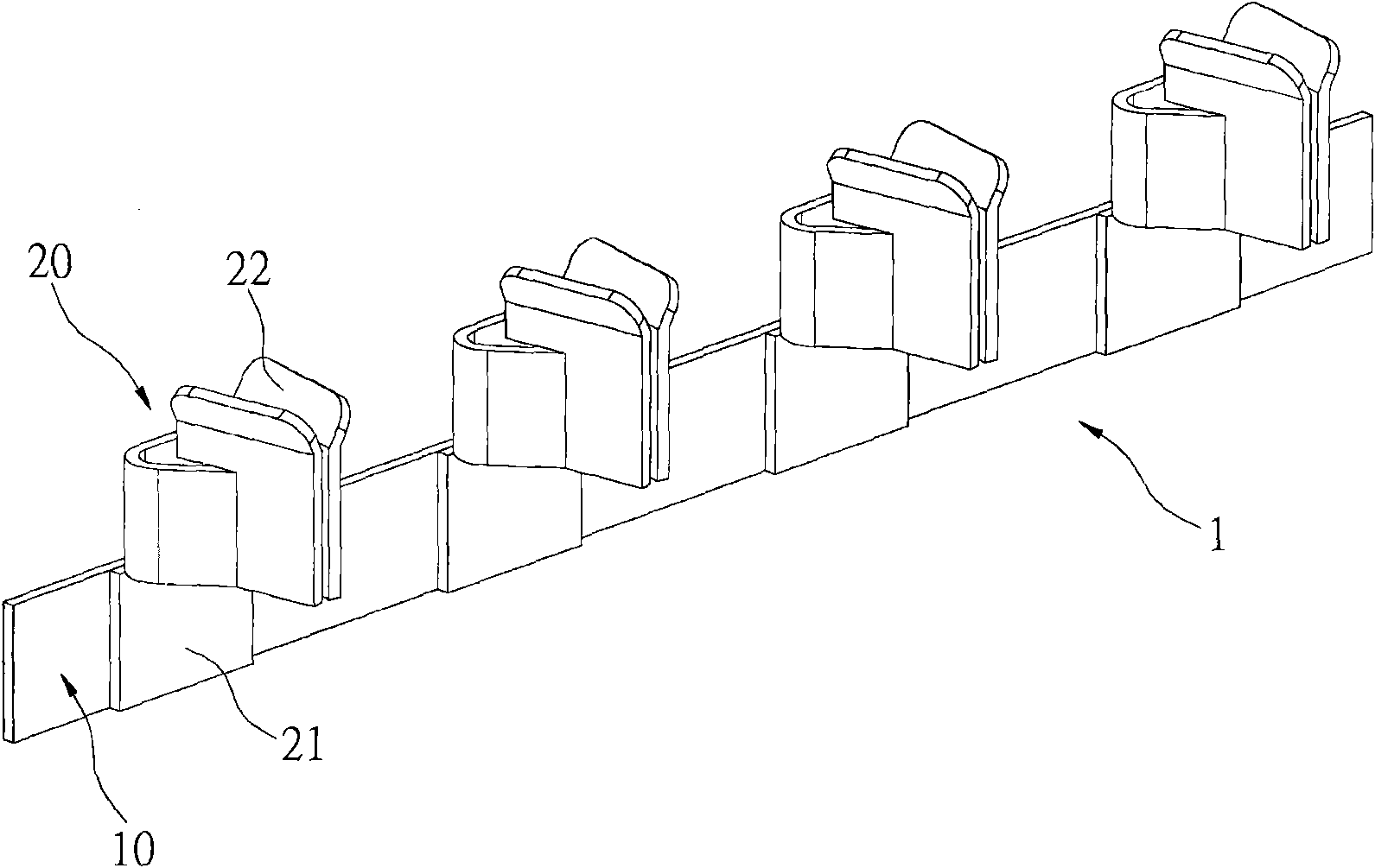
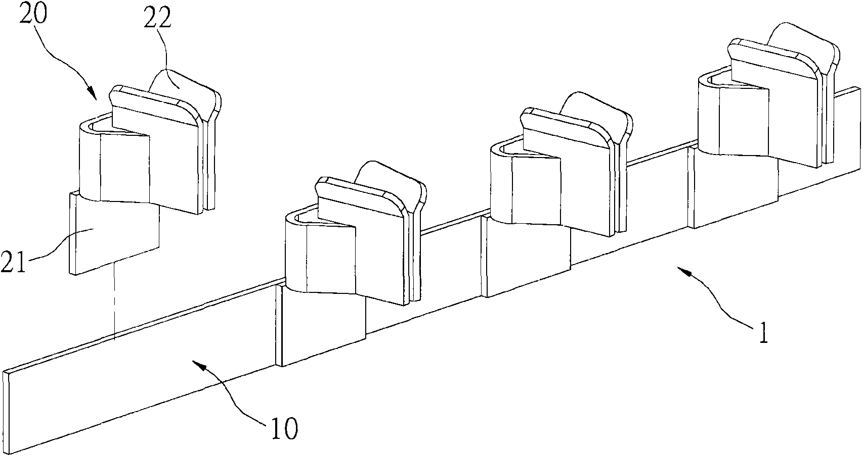
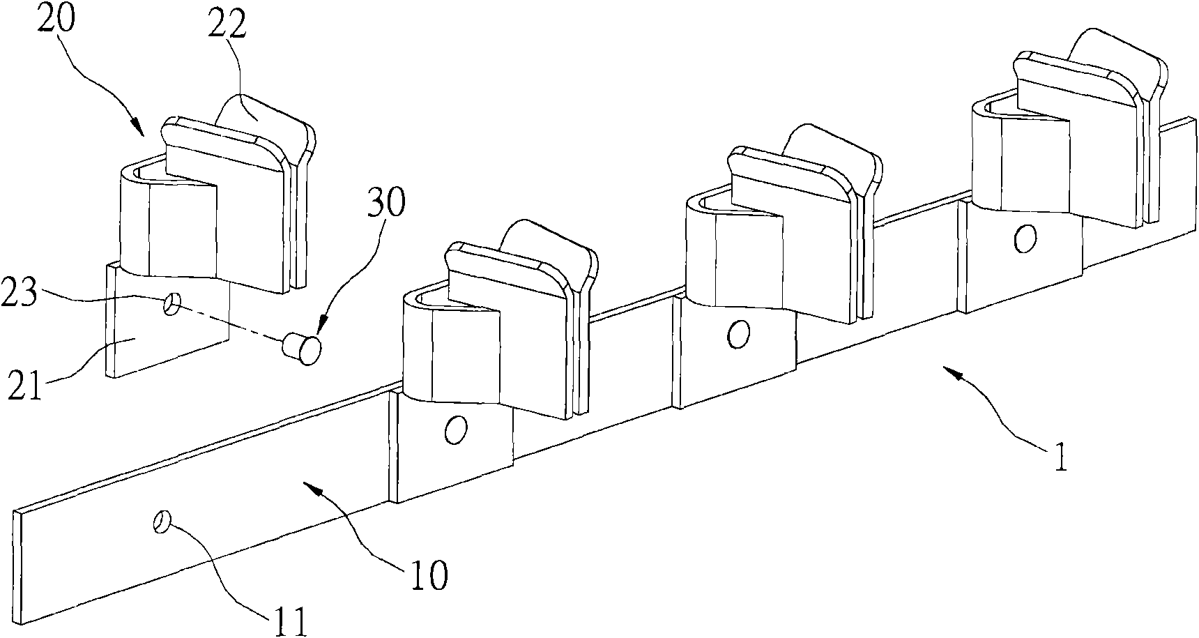
[0036] see figure 1 and figure 2 , which shows the conductive sheet structure 1 of the present invention, which includes: a connecting sheet 10 and a plurality of contact units 20 .

[0037] The conductive sheet structure 1 can be installed in a power socket (not shown), the connecting piece 10 is used to electrically connect with the power line of the power socket, and each contact unit 20 is respectively corresponding to the socket of the power socket hole.

[0038] The connection piece 10 and the contact unit 20 are made of metal materials with high conductivity, such as copper, and the connection piece 10 and the contact unit 20 can be made of different metal materials. Both the connecting piece 10 and the contact unit 20 are manufactured into their required structural shapes by a punching machine.

[0039] The connecting piece 10 is an elongated sheet body, which is formed by punching a metal plate with a width approximately the same as that of the connecting piece 10...


PUM


Abstract

The invention relates to a conducting strip structure which is installed in a power socket and comprises a connecting strip and a plurality of contact elements, wherein the contact elements are combined on the connecting strip at intervals; thus, the distance among the contact elements combined on the connecting strip can be easily adjusted according to different design requirements, and the contact elements and the connecting strip can be respectively manufactured by adopting metal sheets of different materials or thickness; and in addition, the distance among the contact elements is not formed by punching and removing materials, thereby reducing the generation of waste materials in the punching process.

Description

technical field [0001] The invention relates to a conductive sheet structure, in particular to a conductive sheet structure for a power socket. Background technique [0002] As the quality of life of Chinese people improves day by day, every family has more and more electronic products, and these electronic products usually need to be connected to a mains power outlet through a power cord to obtain power before the electronic products can operate. [0003] However, the quantity of mains power outlets in the family is limited, so consumers generally connect the power cords of electronic products through a multi-socket outlet, and then connect the power cords of the multi-socket outlets to the city. on the electrical outlet. [0004] With the increasing usage and demand of porous power sockets, more and more manufacturers are producing and selling porous power sockets, making the market competition of porous power sockets more and more fierce. Therefore, how to reduce the pr...

Claims


Application Information

Patent Timeline
Patent Type & Authority Applications(China)
IPC IPC(8): H01R13/02H01R13/10H01R4/02H01R4/06H01R4/28
Inventor 周义雄许荣辉
Owner POWERTECH INDAL
Why Eureka
Eureka Blog
Learn More