Thermoelectric conversion element, thermoelectric conversion module, and process for producing thermoelectric conversion element

A technology of thermoelectric conversion and manufacturing method, which is applied in the manufacture/processing of thermoelectric devices, junction lead-out materials of thermoelectric devices, thermoelectric devices using only Peltier or Seebeck effect, etc. Occupancy rate, simplification of manufacturing processes, and good economic effects

Active Publication Date: 2010-03-24
MURATA MFG CO LTD
View PDF4 Cites 11 Cited by
  • Summary
  • Abstract
  • Description
  • Claims
  • Application Information

AI Technical Summary

Problems solved by technology

[0018] However, the actual situation is that in the prior art shown in Patent Document 3 and Patent Document 4, although the composition of the oxide thermoelectric conversion material and its firing conditions are described, there is no The combination of n-type and p-type thermoelectric conversion materials necessary for the element and its direct bonding method did not propose a specific plan

Method used


Image

  • Thermoelectric conversion element, thermoelectric conversion module, and process for producing thermoelectric conversion element
  • Thermoelectric conversion element, thermoelectric conversion module, and process for producing thermoelectric conversion element
  • Thermoelectric conversion element, thermoelectric conversion module, and process for producing thermoelectric conversion element

Examples


Embodiment approach 1

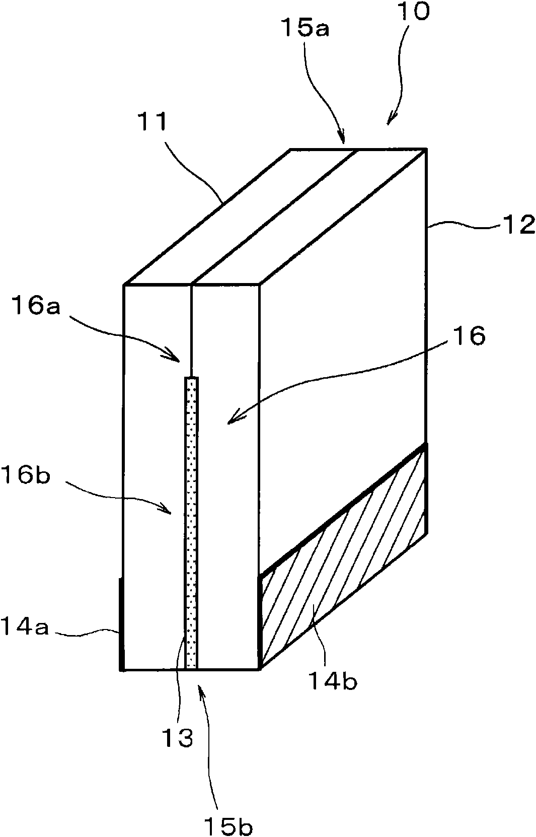
[0062] figure 1 It is a figure which shows the thermoelectric conversion element 10 which is one embodiment (Embodiment 1) of this invention. Such as figure 1 As shown, the thermoelectric conversion element 10 of Embodiment 1 includes a p-type thermoelectric conversion material (hereinafter referred to as "p-type oxide thermoelectric conversion material") 11 formed of a material mainly composed of oxide and a p-type thermoelectric conversion material composed of oxide as a main component. An n-type thermoelectric conversion material (hereinafter referred to as “n-type oxide thermoelectric conversion material”) 12 formed of a material as a main component.

[0063] In addition, in the thermoelectric conversion element 10 according to the first embodiment, in the part region 16a of the junction surface 16 of the p-type oxide thermoelectric conversion material 11 and the n-type oxide thermoelectric conversion material 12, the p-type oxide thermoelectric conversion material 11 a...

Embodiment approach 2

[0095] figure 2 It is a diagram showing a schematic configuration of a thermoelectric conversion module according to Embodiment 2 of the present invention.

[0096] The thermoelectric conversion module 20 of Embodiment 2 has a structure in which a plurality of thermoelectric conversion elements 10 having one p-type oxide thermoelectric conversion material 11 and one n-type oxide thermoelectric conversion material 12 are bonded, and A first electrode 14a and a second electrode 14b are disposed on the lower portion (low temperature side joint portion) 15b.

[0097] Also, although figure 2 shows a structure including three thermoelectric conversion elements 10 composed of a pair of p-type oxide thermoelectric conversion materials 11 and n-type oxide thermoelectric conversion materials 12, but the number of thermoelectric conversion elements 10 constituting the thermoelectric conversion module 20 Not particularly limited.

[0098] In addition, in the thermoelectric conversion...


PUM

PropertyMeasurementUnit
softening pointaaaaaaaaaa

Abstract

This invention provides a thermoelectric conversion element, which has low contact resistance between a p-type thermoelectric conversion material and an n-type thermoelectric conversion material and,at the same time, does not cause oxidation-derived deterioration, and can be used even at an elevated temperature, and a thermoelectric conversion module, and a process for producing a thermoelectricconversion element. A material composed mainly of a substance having a layered perovskite structure represented by a compositional formula of A2BO4 (wherein A represents one or a plurality of elementsincluding at least La; and B represents one or a plurality of elements including at least Cu) is used as a p-type oxide thermoelectric conversion material (11). A material composed mainly of a substance having a layered perovskite structure represented by a compositional formula of D2EO4 (wherein D represents one or a plurality of elements including at least one of Pr, Nd, Sm, and Gd; and E represents one or a plurality of elements including Cu) is used as an n-type oxide thermoelectric conversion material (12). The p-type oxide thermoelectric conversion material, the n-type oxide thermoelectric conversion material, and the composite insulating material (13) are cosintered. A glass having a glass softening point of 550 to 750 DEG C or above is used as a glass constituting the composite insulating material.

Description

technical field [0001] The invention relates to a thermoelectric conversion element, a thermoelectric conversion module and a method for manufacturing the thermoelectric conversion element. Background technique [0002] In recent years, reduction of carbon dioxide has become an important issue in order to prevent global warming, and thermoelectric conversion elements that can directly convert heat into electricity have attracted attention as one of effective waste heat utilization technologies. [0003] In addition, as conventional thermoelectric conversion elements, for example, known Image 6 Shown is a thermoelectric conversion element 50 having a structure including a p-type thermoelectric conversion material 51 , an n-type thermoelectric conversion material 52 , a low-temperature-side electrode 56 , and a high-temperature-side electrode 58 . [0004] In this thermoelectric conversion element 50 , two types of thermoelectric conversion materials 51 and 52 are energy conv...

Claims


Application Information

Patent Timeline
Patent Type & Authority Applications(China)
IPC IPC(8): H01L35/32H01L35/22H01L35/34
CPCH01L35/32H01L35/22H10N10/855H10N10/17
Inventor 林幸子中村孝则
Owner MURATA MFG CO LTD
Why Eureka
Try Eureka