Pneumatic component

A component and pneumatic technology, applied in the direction of engine components, variable displacement pump components, pump components, etc., can solve the problems of not being able to apply mass production, small process reliability, etc., achieve high sealing performance, and save the effect of sealing grease

Inactive Publication Date: 2012-10-10
WABCO GMBH
View PDF0 Cites 0 Cited by
  • Summary
  • Abstract
  • Description
  • Claims
  • Application Information

AI Technical Summary

Problems solved by technology

The disadvantage of this is that this method has such a small process reliability for piston diameters larger than 70mm that the method cannot be applied to mass production

Method used


Image

  • Pneumatic component
  • Pneumatic component
  • Pneumatic component

Examples


Embodiment Construction

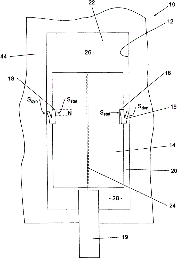
[0020] figure 1 A pneumatic component is shown in the form of a compressor 10 comprising a cylinder 12 , a piston 14 operating within the cylinder 12 , and a grooved ring 16 . The grooved ring 16 is fixed in a groove 18 surrounding the piston 14 . Piston 14 can reciprocate on connecting rod 19 . When the piston 14 is pushed into the cylinder 12, the grooved ring 16 seals the gap 20 between the cylinder 12 and the piston 14, so that the air 22 inside the cylinder 12 is compressed to the air pressure p. Compressed air exits the cylinder through a non-return valve, not shown, and as the piston 14 moves out of the cylinder 12, the air can flow through the grooved ring 16 and through the gap 20 to be compressed in the following stroke.

[0021] The piston 14 is produced from plastic in an injection molding process, which results in the formation of molding surface flashes 24 , which are schematically drawn in dashed lines and extend along the longitudinal axis of the piston 14 an...


PUM


Abstract

The invention relates to a pneumatic component with a cylinder (12), a piston (14) running in the cylinder and a grooved ring (16), which seals the piston (14) from the cylinder (12) and has a static side (Sstat) and a dynamic side (Sdyn). According to the invention, the grooved ring (16) has at least two concentric microlips (38) on the static side (Sstat).

Description

technical field [0001] The invention relates to a pneumatic component with a cylinder, a piston running in the cylinder and a grooved ring which seals the piston relative to the cylinder and has a static side and a dynamic side. Background technique [0002] Such pneumatic components are used, for example, in the form of compressors, in particular as piston air compressors, in trucks or passenger cars. The piston of the compressor has a surrounding groove into which the grooved ring fits. The grooved ring seals the piston against the cylinder. In order to reduce production costs, the pistons for such compressors are partly produced by injection molding. In addition, molding surface burrs running in the longitudinal direction of the piston remain. This molding surface burr must be removed by cutting so that the separately produced rubber groove can be fitted onto the piston. Without deburring of the molding surface, the grooved ring is not seated in an adequately sealing ...

Claims


Application Information

Patent Timeline
Patent Type & Authority Patents(China)
IPC IPC(8): F16J9/20F04B53/14F16J15/32
CPCF04B53/143F04B39/0005Y10T29/49265
Inventor 延斯-托尔斯滕·格罗瑙米可·霍伊里希蒂诺·维格斯
Owner WABCO GMBH
Why Eureka
Try Eureka