
Drive device for hybrid vehicle

A hybrid vehicle and driving device technology, which is applied to hybrid vehicles, power devices, electric power devices, etc., can solve the problems of high price of the driving device, large size of the motor, and high price, so as to reduce the number of assembly operations and reduce the price , the effect of cost reduction

Inactive Publication Date: 2010-03-24
AISIN AW CO LTD +1
View PDF1 Cites 10 Cited by
  • Summary
  • Abstract
  • Description
  • Claims
  • Application Information

AI Technical Summary

Problems solved by technology

Therefore, the drive unit becomes expensive
In addition, since there is a limit to the size of the reduction ratio that can be set with respect to the size in the planetary gear mechanism, the motor requires high performance, so the volume of the motor becomes large and the price becomes high
As a result, the overall size of the drive unit becomes larger and the price becomes higher

Method used


Image

  • Drive device for hybrid vehicle
  • Drive device for hybrid vehicle
  • Drive device for hybrid vehicle

Examples


Embodiment Construction

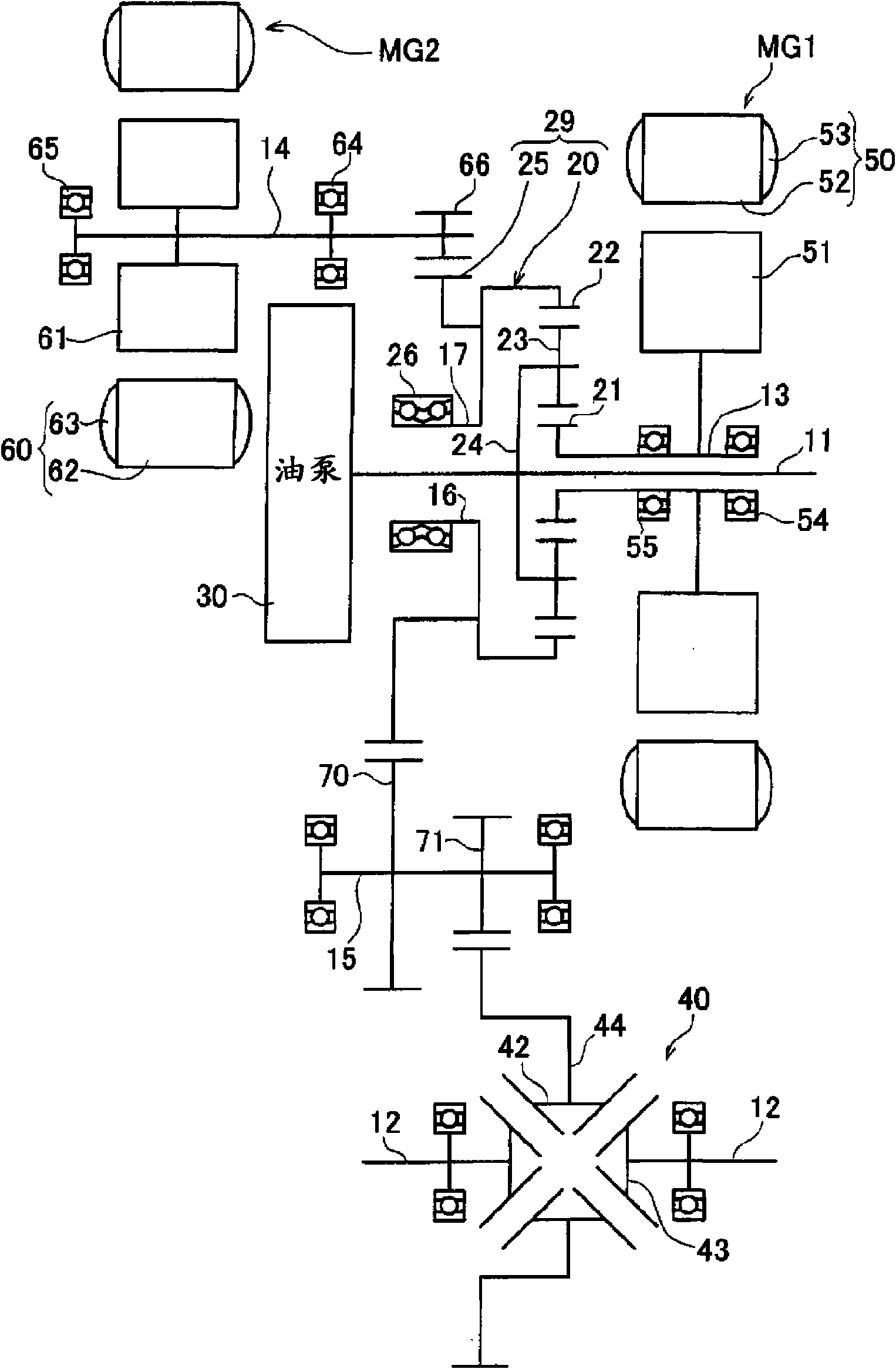
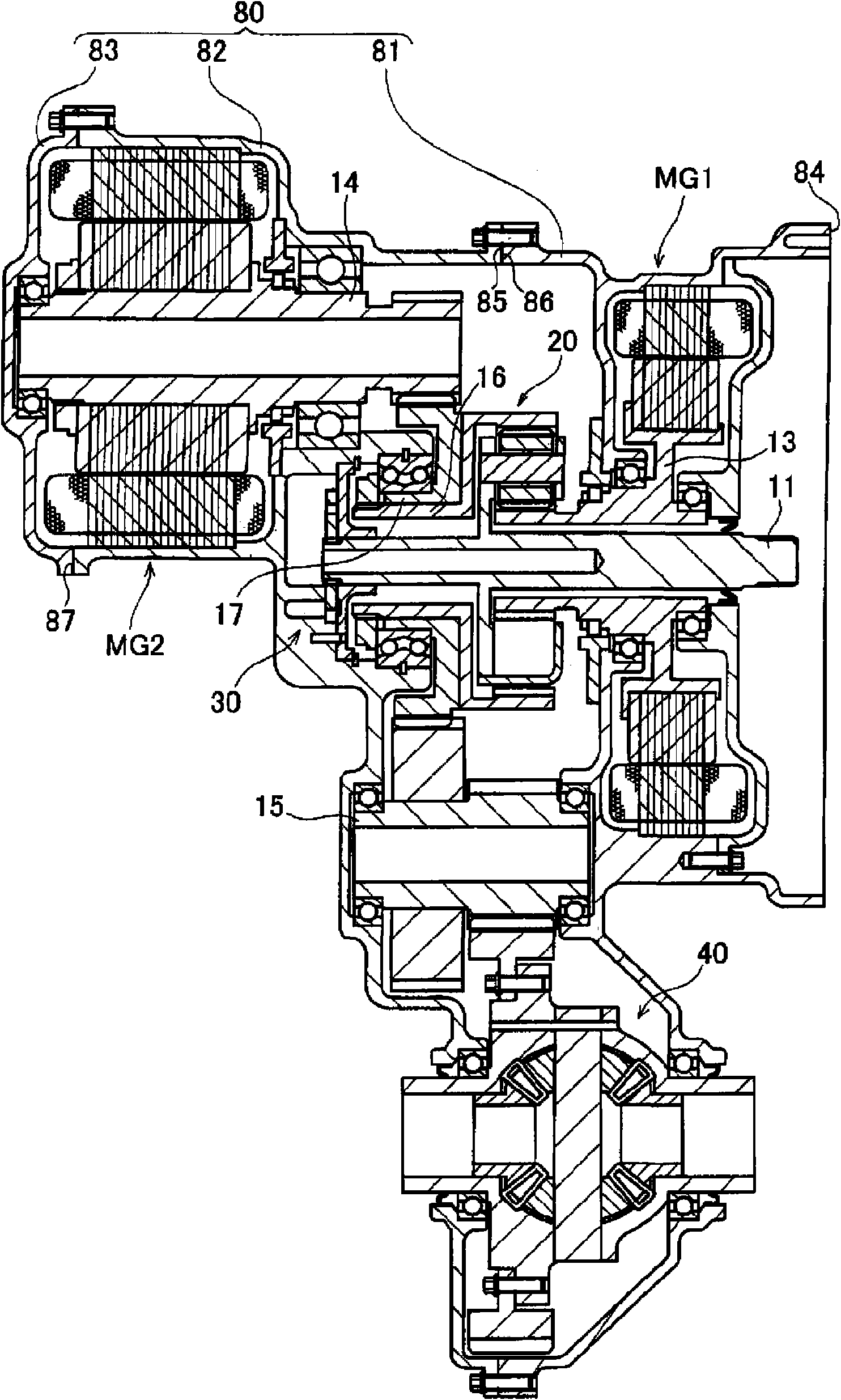
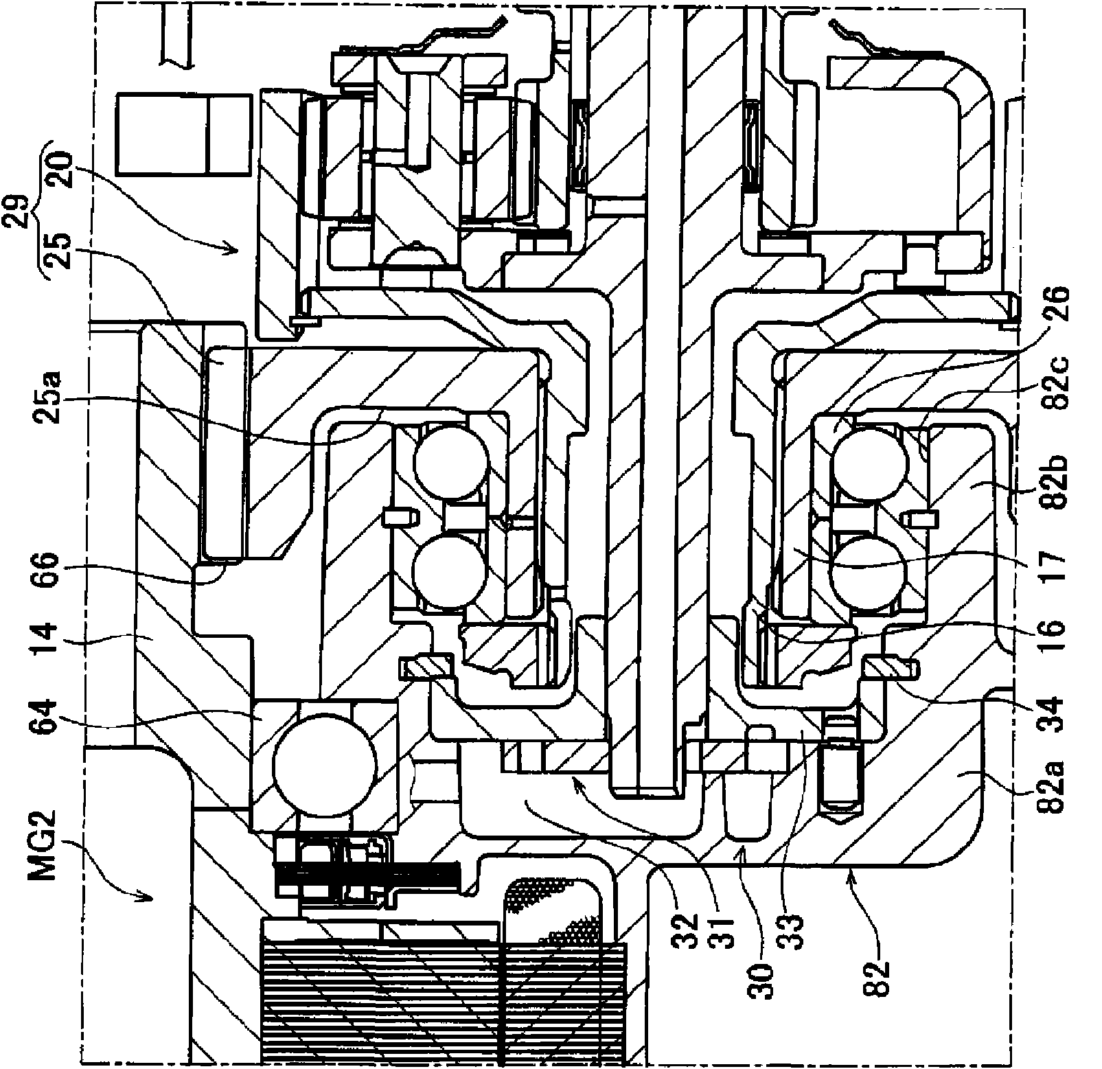
[0041] Hereinafter, the best mode for actualizing the driving device for a hybrid vehicle according to the present invention will be described based on the drawings. This embodiment is a transverse drive unit mounted on a front-engine front-wheel drive (FF) vehicle. Here, regarding the driving device of the embodiment, refer to Figure 1 to Figure 4 Be explained. figure 1 It is a schematic diagram of the driving device of the embodiment. figure 2 It is a cross-sectional view showing a schematic configuration of the drive device according to the embodiment. image 3 It is an enlarged sectional view near the oil pump. Figure 4 It is a layout diagram showing the layout relationship of components included in the drive device according to the embodiment.

[0042] The driving device of this embodiment, such as figure 1 As shown, it includes an input shaft 11 for inputting power from an engine (not shown), a motor generator MG1, a motor generator MG2, and a differential gear d...


PUM


Abstract

A small size, low cost drive device for a hybrid vehicle. The drive device is constructed such that a motor generator (MG1), a differential gear device (20), and an oil pump (30) are arranged in thatorder from the engine side so as to be coaxial with an input shaft (11), that a motor generator (MG2) is placed on the opposite side of a gear mechanism (29) from the motor generator (MG1) so as to belocated on a shaft different from and parallel to the input shaft (11), and that motor bearings (64, 65) supporting a rotor shaft (14) of the motor generator (MG2) are arranged outside the motor generator (MG2). The oil pump (30), one of the components forming a fist shaft, is radially overlapped on the motor generator (MG2) and axially overlapped on the bearing (64) of the motor generator (MG2).

Description

technical field [0001] The present invention relates to a drive device mounted on a hybrid vehicle using an engine and an electric motor as drive sources. Background technique [0002] In the driving device of a hybrid vehicle using an engine (internal combustion engine) and an electric motor as power sources, it is necessary to transmit the power of the two systems to the drive shaft connected to the drive wheels through the differential device, and as its power train structure, proposed various structures. As one of them, there is, for example, a vehicle drive device in which a generator, a planetary gear mechanism for power splitting, and a planetary gear mechanism for motor deceleration are arranged coaxially with the input shaft (the output shaft of the engine) in order from the engine side. and an electric motor (Patent Document 1). In this vehicle driving device, the power from the engine and the power from the electric motor whose torque is amplified by the planeta...

Claims


Application Information

Patent Timeline
IPC IPC(8): B60K6/40B60K6/26B60K6/365B60K6/405B60K6/445H02K7/116B60K6/36B60K17/04B60L50/16F16H57/02F16H57/021F16H57/023F16H57/04
CPCY02T10/6239H02K7/116B60K6/405B60K6/26B60K1/02B60L11/08B60L11/14H02K7/08H02K7/006Y02T10/7077Y02T10/641B60K6/40B60K6/365B60K6/445B60L50/13B60L50/16Y02T10/62Y02T10/64Y02T10/7072Y02T10/70
Inventor 三治广明佐田夏木新智夫土田充孝驹田英明
Owner AISIN AW CO LTD
Learn More