
Cylinder apparatus

A cylinder device and cylinder technology, which are applied to brake transmission devices, cylinders, fluid pressure actuating devices, etc., can solve the problems of increased sliding resistance of pistons and deteriorated running feeling, and achieve reduction of invalid stroke and increase of sliding resistance. , simple shape effect

Active Publication Date: 2010-03-24
HITACHI ASTEMO LTD
View PDF3 Cites 4 Cited by
  • Summary
  • Abstract
  • Description
  • Claims
  • Application Information

AI Technical Summary

Problems solved by technology

However, the sliding resistance to the piston increases so that there is a problem that the running feeling deteriorates

Method used


Image

  • Cylinder apparatus
  • Cylinder apparatus
  • Cylinder apparatus

Examples


Embodiment Construction

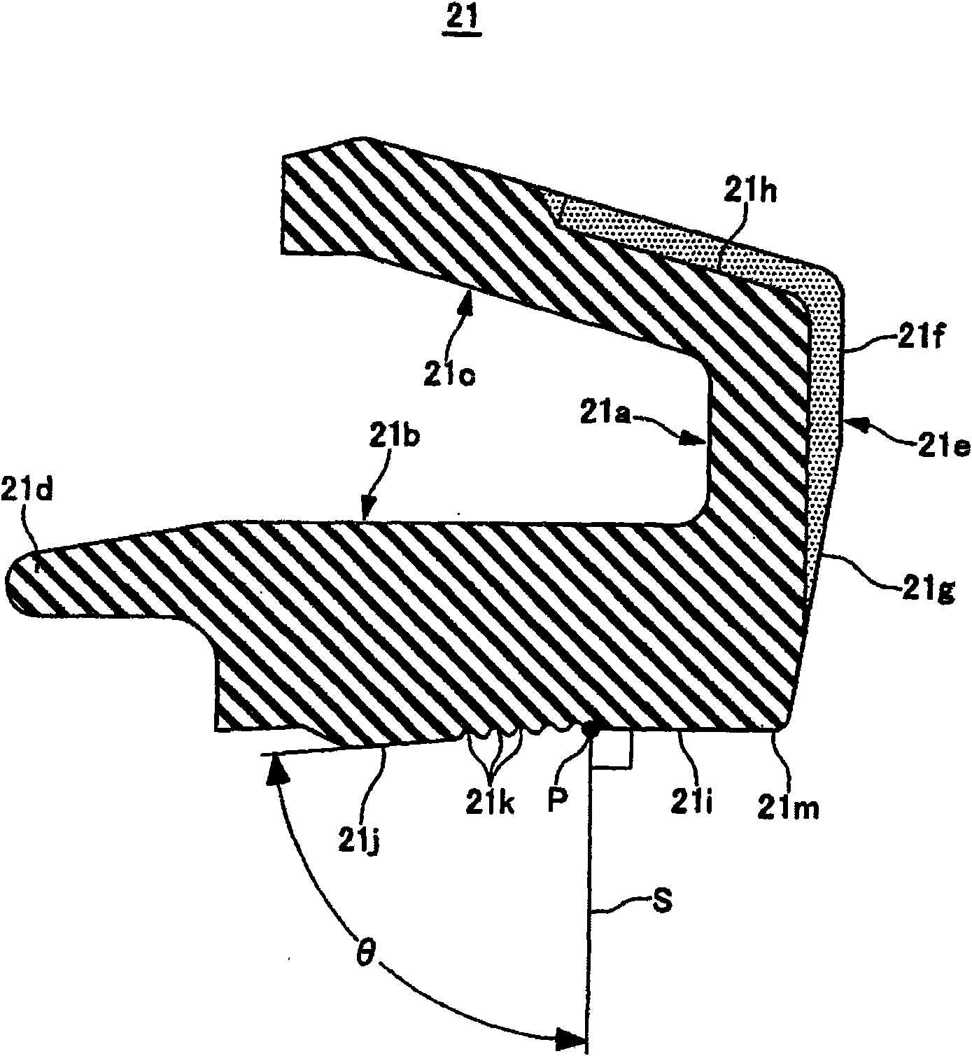
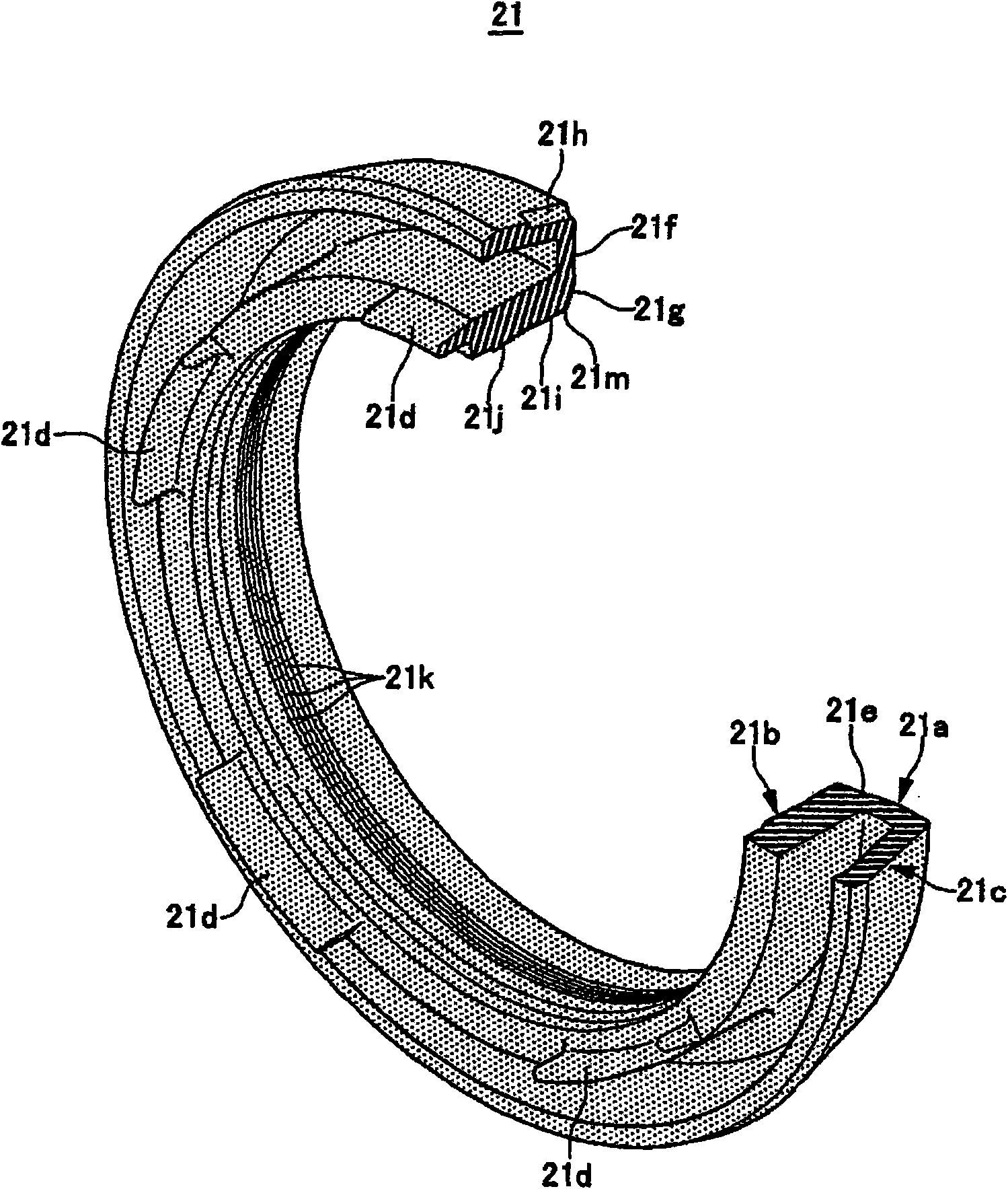
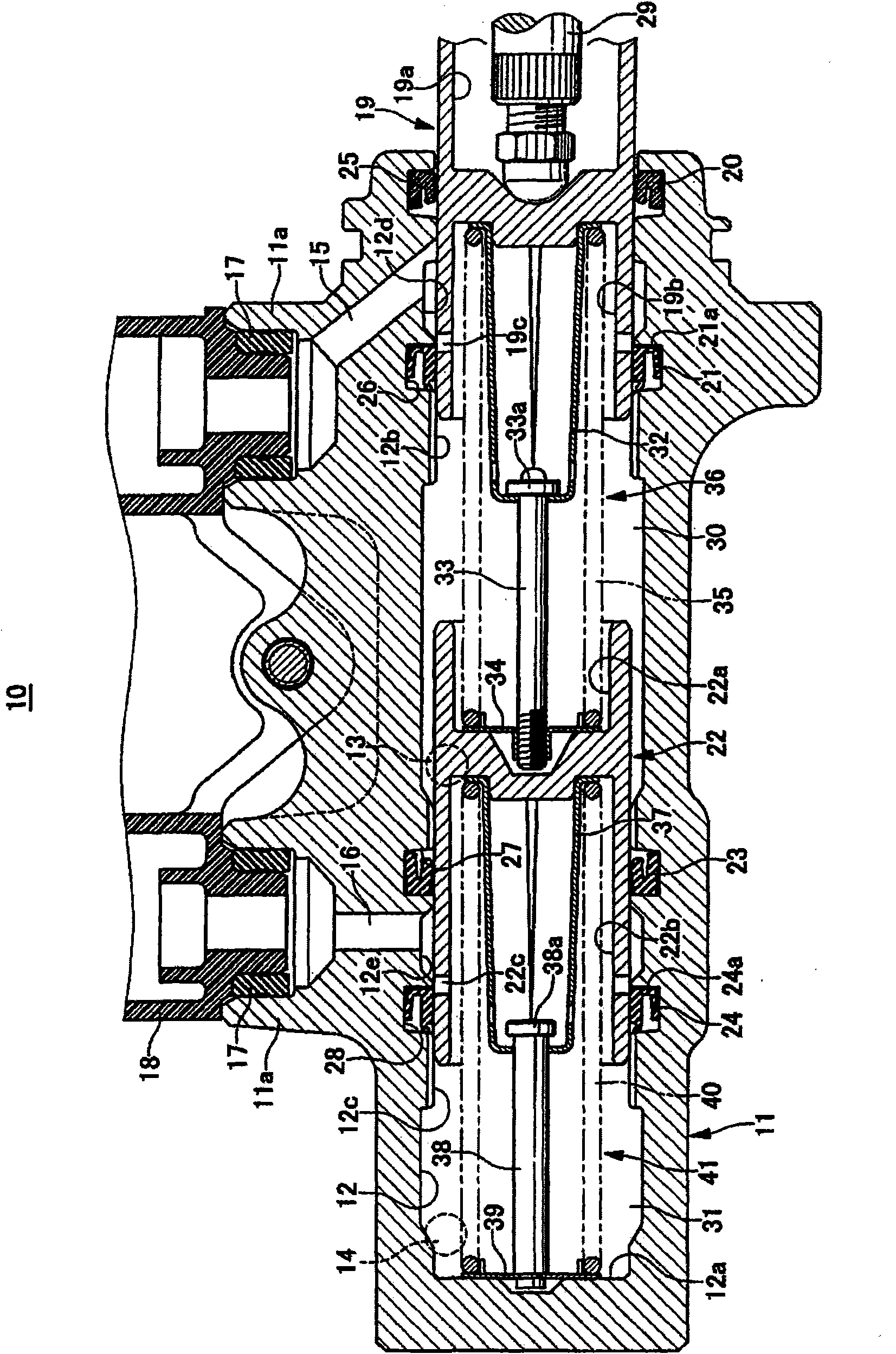
[0050] Figure 1 to Figure 5C An embodiment in which the cylinder device of the present invention is applied to a plunger-type vehicle hydraulic master cylinder is shown.

[0051] First, as image 3As shown, in the hydraulic master cylinder 10 , a bottomed cylinder bore 12 is formed in the cylinder body 11 . The cylinder main body 11 is formed with a first output port 13 opened to a middle portion along the axial direction of the cylinder of the cylinder bore 12 and a second output port 14 opened on the bottom side of the cylinder bore 12 . In addition, a pair of bosses are provided to protrude on the upper portion of the cylinder main body 11 . First and second fluid passage holes 15 and 16 communicating with the cylinder bore 12 are provided in the two bosses 11a and 11a, respectively. The accumulator 18 is connected to the bosses 11a and 11a via grommet seals 17 and 17 .

[0052] In the cylinder bore 12, the first plunger 19 (piston) can be slidably inserted via the fir...


PUM


Abstract

A cup seal 21 includes a base portion 21a disposed on a cylinder bore opening portion side of a seal groove, and an inner lip portion 21b extended from an inner circumferential side of the base portion toward a cylinder bore bottom portion and having an inner circumferential surface slidably abutting against an outer circumferential surface of a piston. In a state where the cup seal 21 is fitted into the seal groove and a plunger 19 is inserted into a cylinder bore 12, an abutting force maximum portion 21m where an abutting force against the plunger 19 becomes maximum within an inner circumferential surface of the cup seal 21 is provided on an end portion on the cylinder bore opening portion side of an inner circumferential surface part of the base portion 21a.

Description

technical field [0001] The present invention relates to a cylinder device, in particular to a cylinder device in which a piston is movably inserted into a cylinder bore via a cup-shaped seal. Background technique [0002] In a cylinder device, there is known an annular seal groove formed on an inner circumferential surface of a cylinder bore into which a piston can be movably inserted, and a cup seal capable of slidably sealing a portion between the cylinder bore and the piston The parts are loaded into the sealing groove. [0003] Generally, as described in Japanese Patent Unexamined Publication No. JP-A-2004-231093, the seal groove includes: a seal groove bottom surface extending along a circumferential surface; a bottom side surface on the bottom side of the cylinder bore; an opening side surface on the side of the opening portion of the cylinder bore; and a seal groove opening opening to the piston. Also, the cup seal includes: a base portion disposed on the cylinder b...

Claims


Application Information

Patent Timeline
Patent Type & Authority Applications(China)
IPC IPC(8): F16J10/02F16J15/32F15B15/14B60T11/16B60T11/236F16J15/3236
CPCB60T11/236
Inventor 花冈光裕
Owner HITACHI ASTEMO LTD
Learn More