Signal transmitter for a filling level sensor

A technology for signal generators and liquid level sensors, which can be used in buoy liquid level indicators, sliding contact resistors, etc., and can solve the problems of high manufacturing costs

Active Publication Date: 2010-03-17
VTESCO TECH GMBH
View PDF0 Cites 1 Cited by
  • Summary
  • Abstract
  • Description
  • Claims
  • Application Information

AI Technical Summary

Problems solved by technology

However, the disadvantage of this known signal generator is that it consists of many components that need to be installed and thus is very expensive to manufacture.

Method used


Image

  • Signal transmitter for a filling level sensor
  • Signal transmitter for a filling level sensor

Examples


Embodiment Construction

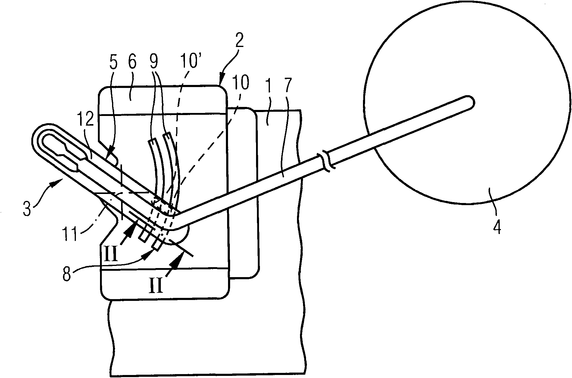
[0016] figure 1 A fill level sensor 2 installed in a vertical wall 1 inside the fuel tank is shown. The level sensor 2 has a float 4 fastened on a lever arm 3 . The float 4 moves with the fuel level (not shown) in the fuel tank and thus deflects the lever arm 3 . The lever arm 3 is pivotably supported on a support 6 with a bow 5 made of plastic and has a lever wire 7 fastened to the bow 5 for supporting the float 4 . The pivoting angle of the lever arm 3 is detected by a signal generator 8 designed as a potentiometer and converted into an electrical signal. The signal generator 8 has two sliding rails 9 , 9 ′ arranged on the support 6 and two sliding contacts 10 , 10 ′ fixed on the bow 5 and electrically connected to each other for bridging the sliding rails 9 ,9'. An electrical signal corresponding to the fuel level is thus present at the carrier 6 and thus at the fixed part of the fill level sensor 2 . The lever arm 3 has a bearing structure in the bearing 6 with a bear...


PUM


Abstract

A signal transmitter (8) for a filling level sensor (2) has two sliding contacts (10, 10') which are manufactured integrally with a holder (12) and with spring elements (15, 15'). This leads to the manufacturing costs of the signal transmitter (8) being particularly low. The sliding contacts (10, 10') are arranged on spring tongues (18, 18') and are connected to one another via a link (17). The spring tongues (18, 18') and the spring elements (15, 15') are therefore arranged in a row and allow the sliding contacts (10, 10') to be prestressed particularly uniformly against sliding tracks (9, 9') of the signal transmitter (8).

Description

technical field [0001] The invention relates to a signal generator for a liquid level sensor of a fuel tank of a motor vehicle, for generating an electrical signal depending on the swing angle of a lever arm of the liquid level sensor supporting a float, the signal generator having: designed for fixing A support with a sliding rail on a vertical wall inside the tank; a sliding contact arranged on the lever arm; a spring element for prestressing the sliding contact against the sliding rail; and a bracket, For supporting the spring element on the lever arm, the two sliding contacts are each arranged on individual spring tongues and are arranged at a distance from one another on a common web. Background technique [0002] Such signal generators are used in particular to determine the fuel level in the fuel tanks of modern motor vehicles and are known from practice. Usually, two sliding contacts bridge the two slide rails of the signal generator, so that subsequent wires can on...

Claims


Application Information

Patent Timeline
Patent Type & Authority Applications(China)
IPC IPC(8): G01F23/36
CPCG01F23/36H01C10/30H01C10/38
Inventor 汉斯-京特·本纳贝恩德·保尔
Owner VTESCO TECH GMBH
Why Eureka
Try Eureka