
Method and arrangement to adjust the pitch of wind turbine blades

A technology of wind turbines and blades, applied in the field of pitch of blades, which can solve problems such as errors and achieve the effect of optimizing performance

Inactive Publication Date: 2010-03-17
SIEMENS AG
View PDF1 Cites 11 Cited by
  • Summary
  • Abstract
  • Description
  • Claims
  • Application Information

AI Technical Summary

Problems solved by technology

Therefore an assumption of a certain wind shear can lead to erroneous results

Method used


Image

  • Method and arrangement to adjust the pitch of wind turbine blades
  • Method and arrangement to adjust the pitch of wind turbine blades
  • Method and arrangement to adjust the pitch of wind turbine blades

Examples


Embodiment Construction

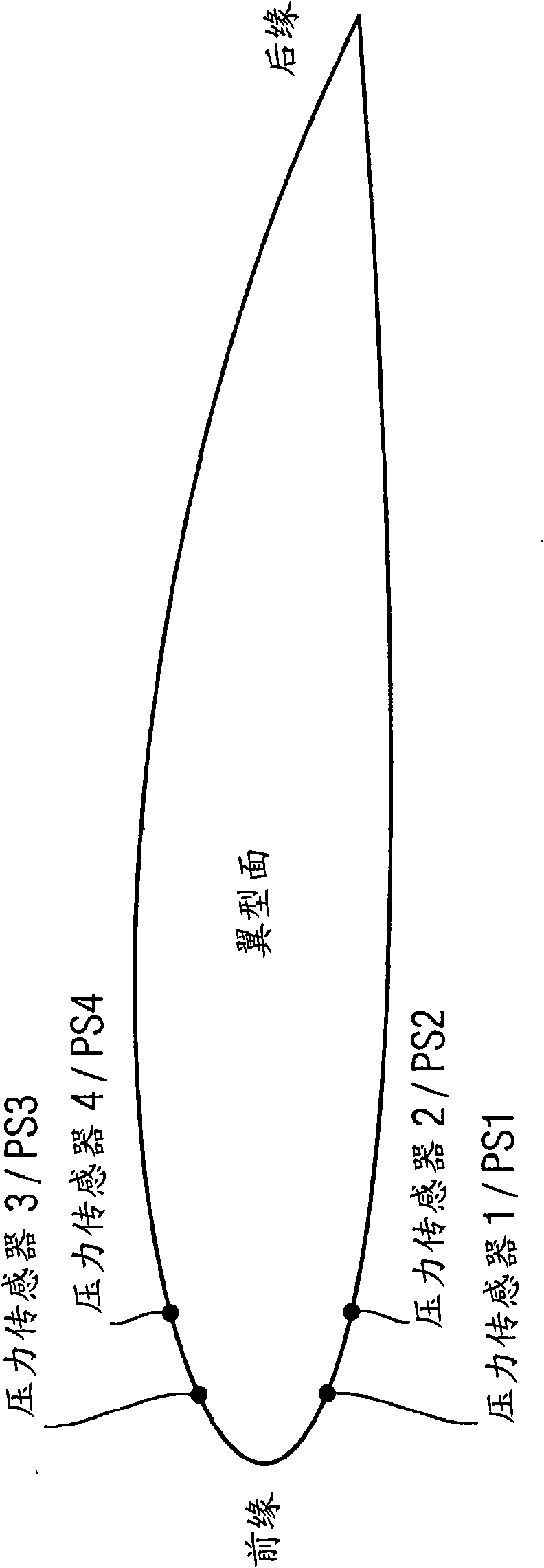
[0031] figure 1 The positions of the four pressure sensors PS1-PS4 according to the invention are shown.

[0032] The blade is shown as an airfoil having a leading edge on a first side and a trailing edge on a second side. Pressure sensors PS1-PS4 are located near the leading edge.

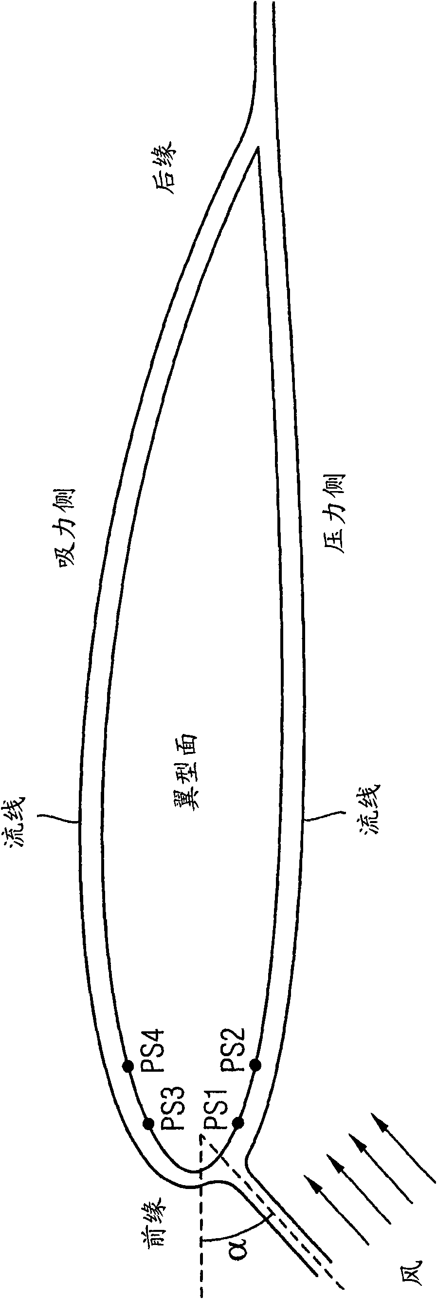
[0033] figure 2 The angle of attack α to be detected and used according to the invention is shown.

[0034] refer to figure 1 , there are four pressure sensors PS1-PS4 near the leading edge of the blade.

[0035] The wind acts on the airfoil, so it is assumed that the pressure sensors PS1 and PS2 are placed on the pressure side for this reason. Correspondingly, pressure sensors PS3 and PS4 are arranged on the suction side.

[0036] The pressure detected by the pressure sensors PS1 and PS2 will be higher than the pressure detected by the pressure sensors PS3 and PS4.

[0037] It is thus possible to determine the pressure difference between the pressure side and the suction side and use thes...


PUM


Abstract

A method and an arrangement to adjust a pitch of blades (3) being used by a wind-turbine (1,2). Pressure is measured at a pressure-side and at a suction side of a blade (3). The measured pressures areused to determine an actual angle-of-attack (alpha) of the wind acting on the blade (3). The angle-of-attack (alpha) is used to adjust the pitch of the blade (3) to optimize a performance of the wind-turbine (1,2).

Description

technical field [0001] The present invention relates to a method of controlling the pitch of blades used in a wind turbine. Background technique [0002] The wind loads acting on pitch-controlled wind turbines below rated power depend on the ideal pitch strategy. Furthermore, the power production of pitch-controlled wind turbines below rated power also depends on the optimal pitch strategy. The blades of the wind turbine are designed for this pitch strategy, and the profile of the blade is designed for the desired value of Cp, which is the "power coefficient". This is the ratio of the power extracted by the wind to the total power available in the wind. The theoretical maximum value of Cp for an ideal wind turbine is the "Bates limit", with a value of 16 / 27, or about 59%. [0003] GB 2067247A describes a pitch control in which pressure probes mounted at the rotor blade surface are used to adjust the blade pitch. A pressure probe is mounted near the tip portion of the bla...

Claims


Application Information

Patent Timeline
Patent Type & Authority Applications(China)
IPC IPC(8): F03D7/00
CPCF05B2270/324Y02E10/723F05B2260/80F05B2270/3015F03D7/0224Y02E10/72
Inventor D·E·尼尔森
Owner SIEMENS AG
Learn More