Ultrasonic elastograph imaging method

An ultrasonic elastography and elastography technology, applied in ultrasonic/sonic/infrasonic diagnosis, sonic diagnosis, infrasound diagnosis, etc., can solve the problems of prolonging patient probing time, increasing patient pain, reducing frame frequency, etc., and shortening probing time, improve the efficiency of diagnosis, and improve the effect of diagnosis

Active Publication Date: 2010-03-17
SHANTOU INST OF UITRASONIC INSTR CO LTD
View PDF0 Cites 8 Cited by
  • Summary
  • Abstract
  • Description
  • Claims
  • Application Information

AI Technical Summary

Problems solved by technology

[0010] In the above-mentioned real-time ultrasound elastography, the necessary image processing technology must be set first, and then, in the process of real-time drawing, the generation parameters of ultrasound elastography should be adjusted according to the actual situation to achieve a better image effect, so that doctors can observe and the positioning of the affected area; when the elastic image is generated, the elastic image can no longer form a new elastic image with different generation parameters, thus limiting the optimization and diversification of ultrasound elastography; at the same time, in order to obtain better image effects In order to improve the diagnostic effect, doctors often prolong the visit time of patients, which affects the doctor's work efficiency and increases the pain of patients; if more diagnostic information is needed, different parameters must be used to print multiple groups of pictures Like, this will further prolong the visit time of the patient and further increase the suffering of the patient
[0011] At the same time, in the above-mentioned real-time ultrasound elastography, various algorithms in the image processing technology occupy a very high resource occupancy rate of the ultrasound elastography system, which affects the performance of the ultrasound elastography system in real-time state and reduces the frame rate, so , the image effect of the elastic image generated in real time is difficult to achieve the desired effect

Method used


Image

  • Ultrasonic elastograph imaging method
  • Ultrasonic elastograph imaging method
  • Ultrasonic elastograph imaging method

Examples


Embodiment Construction

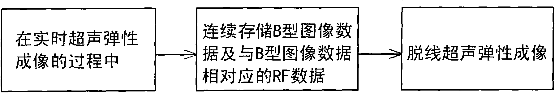
[0052] Such as figure 2 As shown, the principle of the ultrasonic elastography method in this preferred embodiment is: in the process of real-time ultrasonic elastography, continuously store B-type image data and RF data corresponding to the B-type image data; then, according to the stored B-type The image data and the RF data are subjected to off-line ultrasound elastography to generate and display elastic images with different generation parameters.

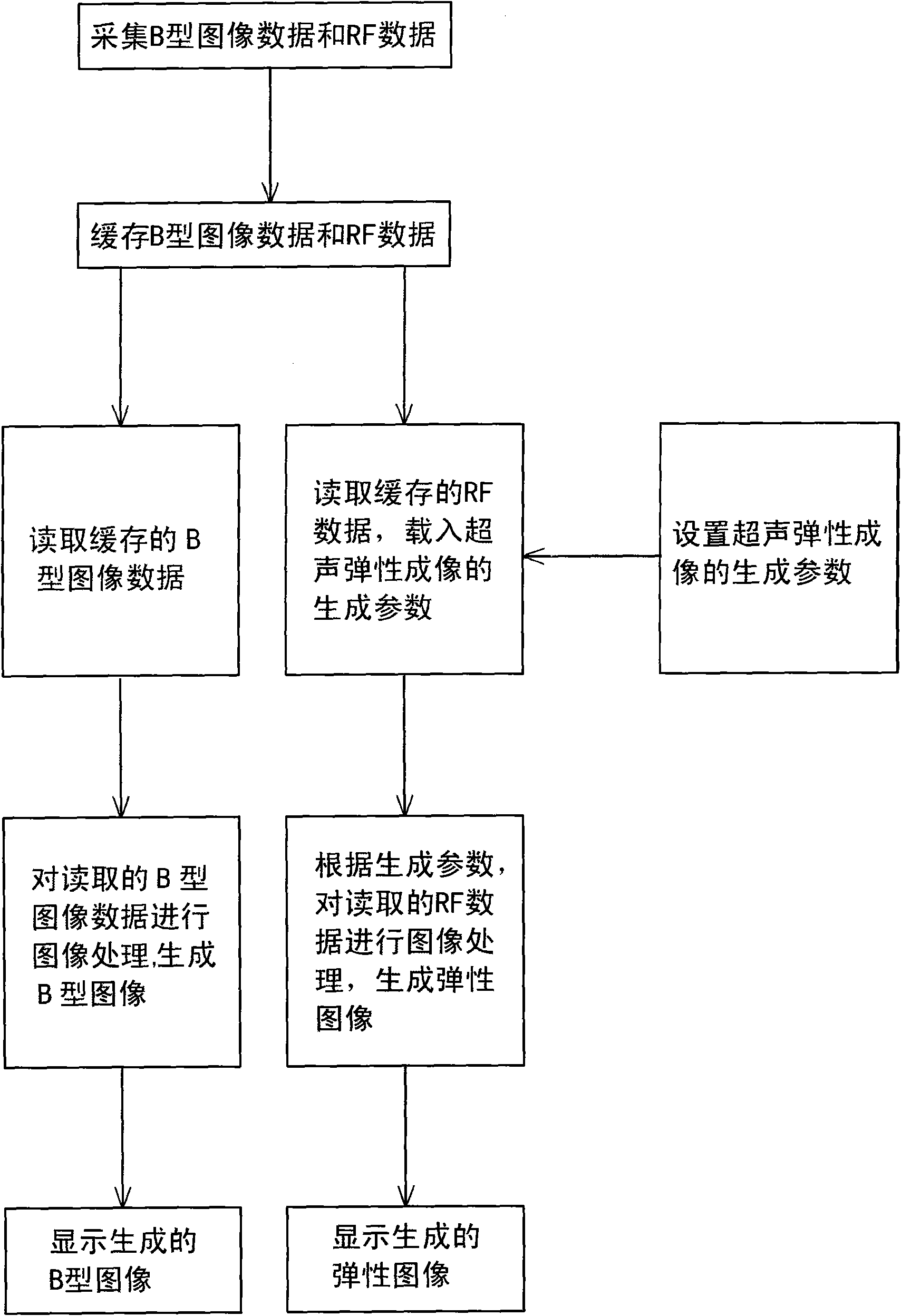
[0053] Such as image 3 As shown, when the ultrasonic elastography method of the present invention is in real-time mode,

[0054] The real-time ultrasound elastography includes the following steps:

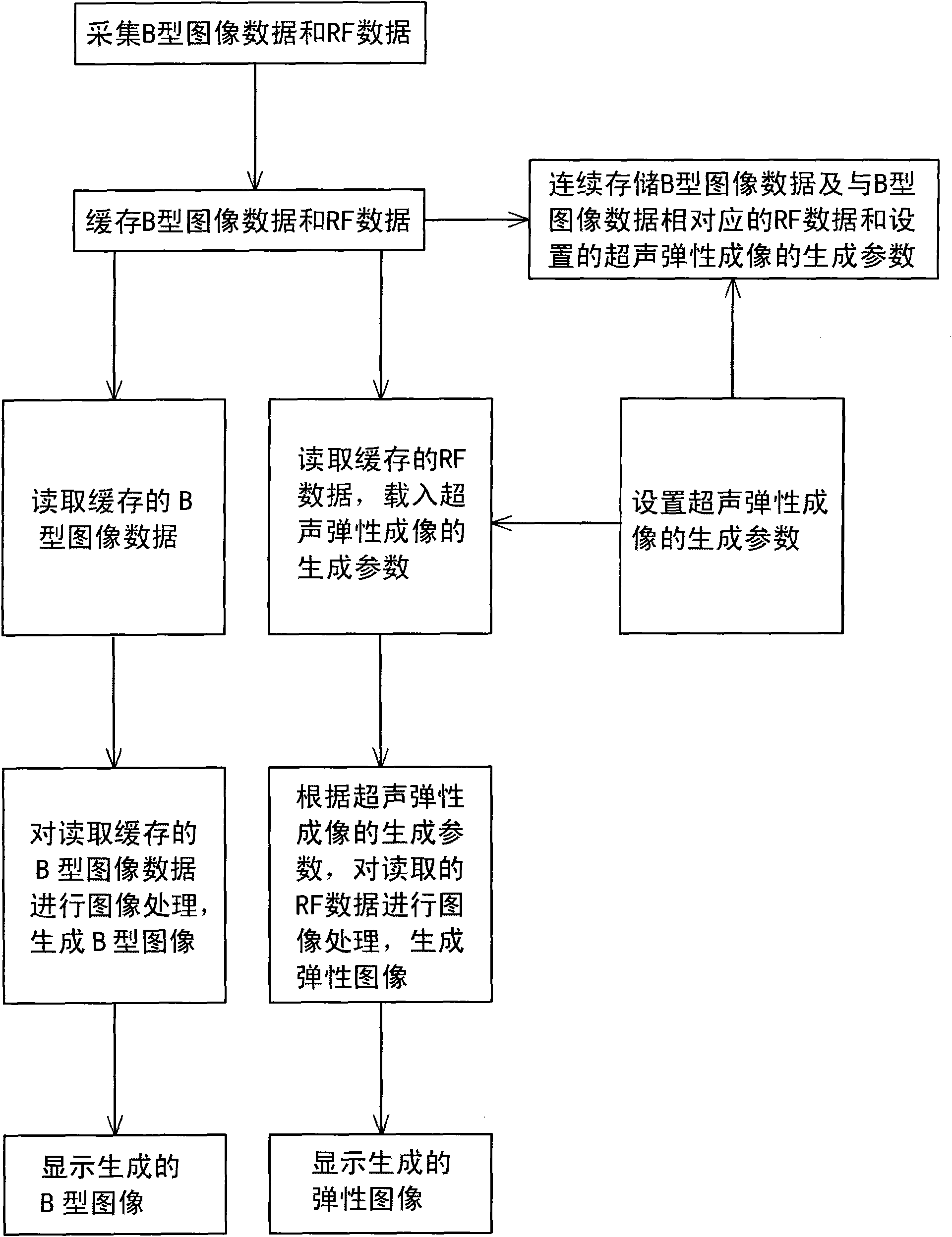
[0055] (1) collecting B-type image data and RF data;

[0056] (2) cache B-type image data and RF data;

[0057] (3) setting the generation parameters of ultrasound elastography;

[0058] (4) Continuously storing the B-type image data and the RF data corresponding to the B-type image data; and storing the set ultrasonic elasto...


PUM


Abstract

An ultrasonic elastograph imaging method comprises the following steps: continuously storing B-type image data and RF data corresponding to the B-type image data during the real-time ultrasonic elastograph imaging process; and then performing off-line ultrasonic elastograph imaging according to the stored B-type image data and the RF data so as to generate and display an elastograph image with different generated parameters. In the method, off-line ultrasonic elastograph imaging can be performed according to the stored RF data and the B-type image data under an off-line status; the elastographimage with different generated parameters can be generated and displayed by adjusting the generated parameters of the ultrasonic elastograph image; during the generation process of the off-line ultrasonic elastograph image, the frame number of the RF data is in a one-to-one relationship with that of the B-type image data, so a B-type image can be taken as reference of the elastograph image; and finally the more optimized elastograph images can be obtained according to the RF data and the generated parameters by selecting an image processing algorithm.

Description

technical field [0001] The invention relates to an imaging method of medical ultrasonic technology, more specifically, to an ultrasonic elastic imaging method. Background technique [0002] The frequency of ultrasound is high, the wavelength is short, and it can propagate along a straight line like light, making it possible for people to emit ultrasound in a certain direction; at the same time, ultrasound can propagate smoothly in human tissue, and ultrasound encounters different media. Reflected waves will occur at the interface; therefore, ultrasonic imaging technology is widely used in the field of medical imaging diagnosis. [0003] Among the existing ultrasound imaging techniques, ultrasound elastography is a commonly used ultrasound imaging technique. The basic principle of ultrasound elastography is: embed the ultrasound probe in a squeeze plate, compress the tissue along the longitudinal direction of the probe, and collect the radio frequency signals before and afte...

Claims


Application Information

Patent Timeline
Patent Type & Authority Applications(China)
IPC IPC(8): A61B8/00
Inventor 杨金耀郑永平赵少武李德来蔡泽杭郭境峰
Owner SHANTOU INST OF UITRASONIC INSTR CO LTD
Why Eureka
Try Eureka