
Swirler

A swirler and burner technology, which is applied in the direction of burners, combustion methods, combustion chambers, etc., to achieve the effect of improving the mixing of fuel and air

Inactive Publication Date: 2012-01-04
SIEMENS AG
View PDF0 Cites 0 Cited by
  • Summary
  • Abstract
  • Description
  • Claims
  • Application Information

AI Technical Summary

Problems solved by technology

Although existing technologies for reducing NOx emissions from gas turbine engines are moving in the right direction, there is still a need for further improvement

Method used


Image

  • Swirler
  • Swirler
  • Swirler

Examples


Embodiment Construction

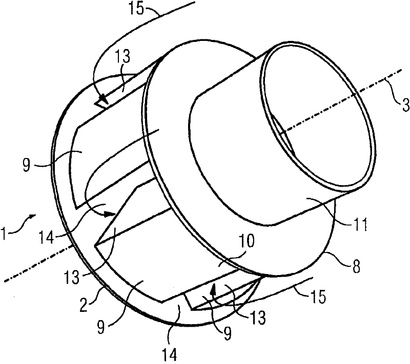
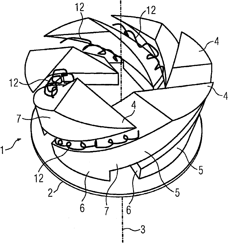
[0018] Referring to Fig. 1, it shows a typical radial swirler 1 in the prior art. The rotating blades 9 of the radial swirler 1 are arranged on the first disk 2 perpendicular to the central axis 3 of the swirler 1 body. The blade 9 is fan-shaped, and the blade has a substantially triangular cross-section 4 (see image 3 ), rectangular sides 13 and slightly curved outer surfaces 10. The rotor blades 9 are fastened to the second disc 8 with their sides shown facing away from the first plate 2 . The swirler channels 14 are formed by the opposing sides 13 of the swirler vanes 9 , the surface of the first disk 2 and the surface of the second disk 8 . The second disc 8 is connected to the pre-chamber 11 .

[0019] This configuration of the swirler 1 forces the air flow (as indicated by the arrows) to move radially inwards in the channels 14 towards the central axis 3 of the swirler 1 body. With this simple prior art straight blade geometry, the radial swirler 1 has been able to ...


PUM


Abstract

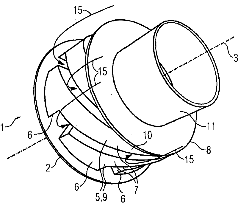
Disclosed is a swirler (1), comprising a plate (2) normal to a central axis (3) of the swirler (1), a plurality of vane footprints (4) arranged on the plate (2) and radially positioned about the central axis (3) and a plurality of twisted vanes (5).

Description

technical field [0001] The present invention relates to a fuel injection system and improvements to further reduce air pollutants such as nitrogen oxides (NOx). Background technique [0002] Air pollution is a worldwide concern, and many countries have enacted stricter laws to further limit pollutant emissions from gas turbine engines, or provide financial or other subsidies for environmentally sound facilities. Although the prior art for reducing NOx emissions from gas turbine engines is headed in the right direction, there remains a need for further improvements. [0003] There are two main methods of reducing the temperature of the combustion flame. The first is to use the fine distribution of fuel in the air to generate a fuel / air mixture with a low fuel ratio. The excess air thermal mass present in the reaction zone of the lean premixed combustor absorbs heat, limiting the temperature rise of the combustion products to a level at which thermal NOx does not form excess...

Claims


Application Information

Patent Timeline
Patent Type & Authority Patents(China)
IPC IPC(8): F23R3/14F23C7/00
CPCF23C7/004F23R3/14F23D2900/14021F23D2900/14701
Inventor N·威尔布里厄姆
Owner SIEMENS AG
Learn More