Blade-type hydraulic transformer controlled by motor

A hydraulic transformer and motor control technology, which is applied in the field of hydraulic transformers and vane hydraulic transformers, to achieve the effects of expanding the application range, easy and precise control, and improving work efficiency

Inactive Publication Date: 2012-06-27
SHANDONG JIAOTONG UNIV
View PDF6 Cites 0 Cited by
  • Summary
  • Abstract
  • Description
  • Claims
  • Application Information

AI Technical Summary

Problems solved by technology

[0004] The technical task of the present invention is to provide a vane with compact structure, uniform flow, low noise, high precision and stable operation, one end can be used in medium and high pressure hydraulic systems, and the other end can be used in low pressure hydraulic systems. Type hydraulic transformer to solve the problem that the pressure at the load end is much smaller than the pressure of the oil supply constant pressure network system, which improves the working efficiency of the hydraulic system, thereby expanding the application range of hydraulic transformers and enriching the types of hydraulic transformers

Method used


Image

  • Blade-type hydraulic transformer controlled by motor
  • Blade-type hydraulic transformer controlled by motor
  • Blade-type hydraulic transformer controlled by motor

Examples


Embodiment Construction

[0019] The present invention will be described in detail below in conjunction with the accompanying drawings and embodiments.

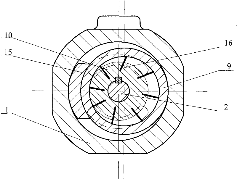
[0020] like figure 1 , 2 , 3, and 4, the vane hydraulic transformer controlled by the motor of the present invention is mainly composed of a housing 1, a rotating shaft 2, a left end cover 3, a first group of flow plates 4, 7 and a first stator 5, a first The rotor 6, the second group of distribution plates 8, 11, the second stator 9, the second rotor 10, the right end cover 12, the gear 13, the first group of blades 14, the wedge plate 15, the second group of blades 16, the motor 17, etc.; The centers of the first rotor 6 and the first stator 5 are fixed and coincident, the width of the first rotor 6 is slightly smaller than the width of the first stator 5, the first rotor 6 is installed in the first stator 5, the first One end of the set of blades 14 is put into the blade groove of the first rotor 6, and the other end is in contact with the inner ...


PUM


Abstract

The invention relates to a blade-type hydraulic transformer controlled by a motor, which comprises a shell, a rotating shaft, a left end cover, a valve plate, stators, rotators, a right end cover, a gear, a wedge-shaped plate, an impeller, a motor and the like. The blade-type hydraulic transformer is characterized in that centers of one set of rotators and the stator are fixed and superposed, thecenters of the other rotators and the stator are all fixed, and if the centers of the rotators and the stators are not superposed, the impeller is radially arranged along the rotators; one rotator isin matched connection with a left half shaft of the rotating shaft through splines, while the other rotator is in matched connection with a right half shaft of the rotating shaft through flat keys; the excircle of one stator is manufactured into a gear shape by taking a long-radius arc center as the center in the range of 150 degrees and form a gear driving pair with the gear, and the outer surface of the other stator is in matched contact with the right lateral surface of the wedge-shaped plate; and the valve plate is arranged on the rotating shaft and tightly pressed on the left lateral surfaces and the right lateral surfaces of the stators, the left end of the rotating shaft is arranged on the valve plate on the left side, the right end of the rotating shaft is arranged on the right end cover, and the left end cover and the right end cover are fixed on the shell through bolts.

Description

(1) Technical field [0001] The invention relates to a hydraulic transformer, in particular to a blade-type hydraulic transformer controlled by a motor, which belongs to the field of machinery. (2) Background technology [0002] A hydraulic transformer is a hydraulic component that realizes pressure conversion in hydraulic transmission. The hydraulic transformer can efficiently convert the input hydraulic energy under a given pressure into the output hydraulic energy under another pressure. Using it can realize the independent control of multiple loads in the constant pressure network, and also make the energy reverse flow , not only can drive linear loads without throttling loss, but also can drive rotary loads. [0003] Existing hydraulic transformers are basically plunger-type structures, with high working pressure above 20MPa and large flow range. They are generally used in high-pressure and large-flow hydraulic systems. They are used in medium and low-pressure hydraulic...

Claims


Application Information

Patent Timeline
Patent Type & Authority Patents(China)
IPC IPC(8): F15B3/00
Inventor 臧发业张玉波梁杰戴汝泉
Owner SHANDONG JIAOTONG UNIV
Why Eureka
Try Eureka