Patient interface systems
A patient interface and patient technology, applied in the direction of respirators, etc., can solve the problems of patients abandoning treatment, patients are difficult to adapt to the interface, patients are unwilling to use masks, etc.
Inactive Publication Date: 2010-02-24
RESMED LTD
View PDF11 Cites 46 Cited by
- Summary
- Abstract
- Description
- Claims
- Application Information
AI Technical Summary
Problems solved by technology
However, patients may find it difficult to adapt to the current interface
For example, once a mask including a headgear and gas delivery hose is installed on a patient to provide the required seal, the patient may have difficulty falling asleep in a familiar, comfortable position
Although masks provide a seal and a defined pressure, patients may be reluctant to use a mask due to concerns about sleeping comfortably while wearing it
This can cause patients to forego treatment
Method used
View moreImage
Smart ImageViewing Examples
Examples
Embodiment Construction
Login to View More PUM
| Property | Measurement | Unit |
|---|---|---|
| Adhesive area | aaaaa | aaaaa |
| Adhesive area | aaaaa | aaaaa |
| Adhesive area | aaaaa | aaaaa |
Abstract
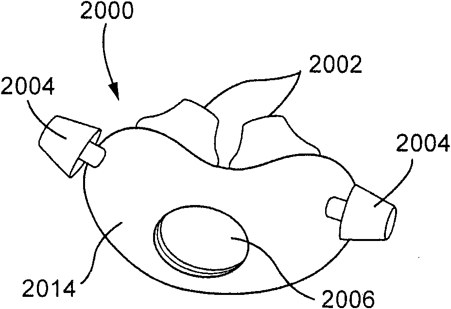
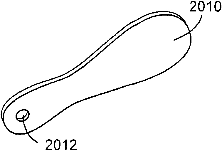
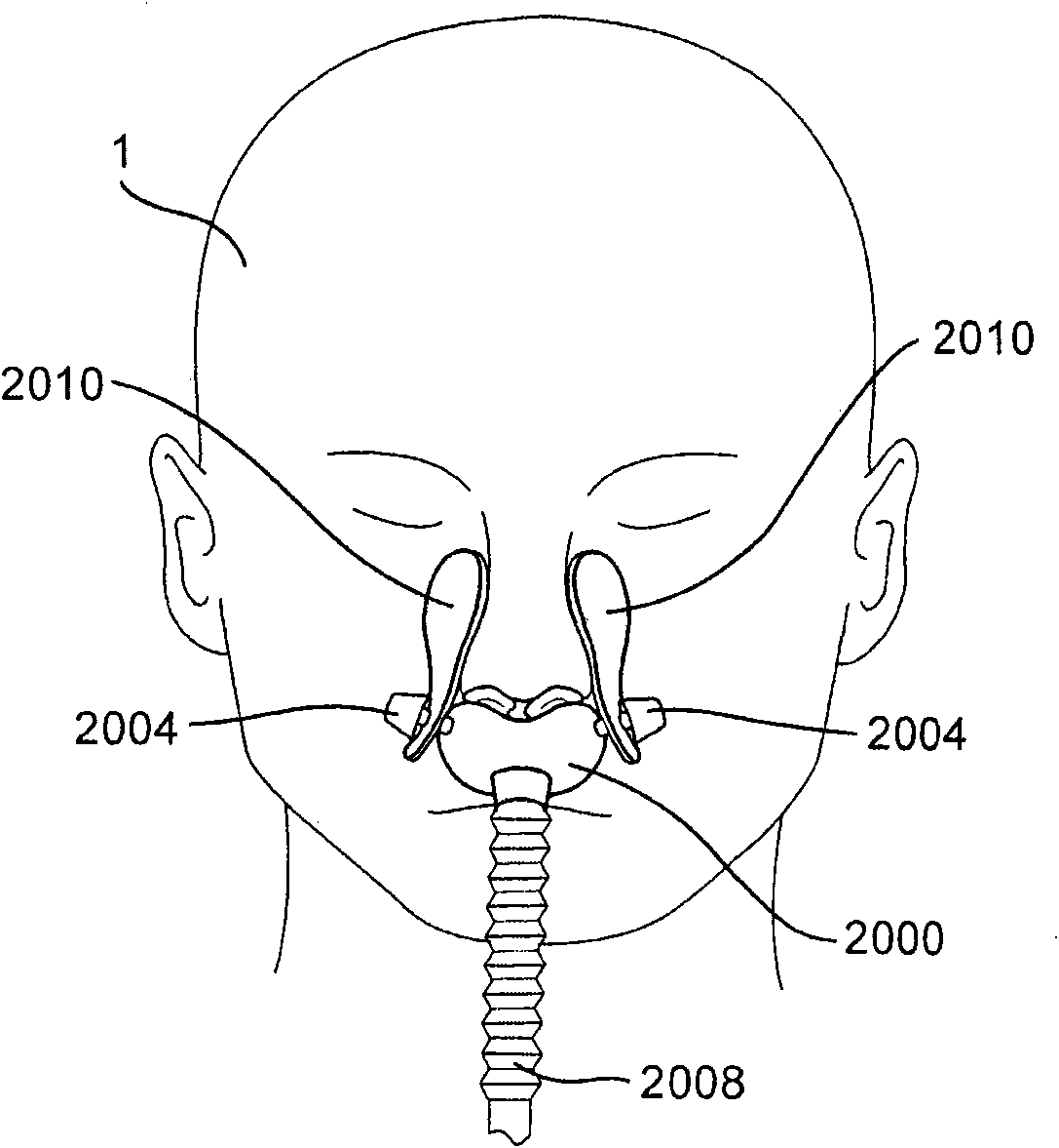
A patient interface system for delivering a flow of breathable gas to a patient includes a patient interface structure configured to sealingly engage the patient's nares; a pair of strips configured to be connected to opposite sides of the patient interface structure; and adhesive configured to secure the patient interface structure in sealing engagement with the patient's nares. The adhesive maybe provided on the strips, and the strips are configured to be adhered to sides of the patient's nose by the adhesive. Another patient interface system includes a first component including adhesive ona first side and hook or loop fastener material on a second side. The patient interface structure includes a second component including a corresponding loop or hook fastener material configured to engage the corresponding hook or loop fastener material of the first strip. A patient interface system for delivering a flow of breathable gas to a patient includes a patient interface structure including a pair of nasal prongs or pillows configured to sealingly engage the patient's nares; and at least one spring configured to bias the nasal prongs or pillows outwards into engagement with the naresof the patient.
Description
[0001] Cross References to Related Applications [0001] This application claims the benefit of U.S. Application No. 61 / 058,659, filed June 4, 2008, and U.S. Application No. 61 / 080,847, filed July 15, 2008, the full texts of which are herein Incorporated by reference. technical field [0002] The present invention relates to patient interface systems for delivering a flow of respiratory air to a patient. The present invention also relates to patient interface systems that may include one or more adhesives and / or patient interface positioning and / or support structures that support the patient interface in engagement with the patient. Background technique [0003] The use of positive airway pressure (PAP) to treat sleep-disordered breathing (SDB) such as obstructive sleep apnea (OSA) is disclosed in US Patent 4,944,310. Treatment with a PAP, which may be continuous positive airway pressure (CPAP), involves the use of a patient interface attached to the patient's face for sup...
Claims
Login to View More Application Information
Patent Timeline
 IPC IPC(8): A61M16/00
Inventor 米希尔·高彻保罗·简·克拉森亚当·维维安·本贾菲尔德彼得·约翰·思文尼理查德·索科洛夫菲利普·罗德尼·夸克杰勒德·迈克尔·鲁梅利斯科特·亚历山大·霍华德罗伯特·爱德华·亨利勒妮·弗朗西斯·多尔蒂恩里科·布兰比拉迪特·海德曼格伦·理查兹伊恩·弗雷德里克·约翰森迈克尔·约翰·瑞德贾斯廷·福尔米卡安德鲁·希姆斯
Owner RESMED LTD
Features
- R&D
- Intellectual Property
- Life Sciences
- Materials
- Tech Scout
- Unparalleled Data Quality
- Higher Quality Content
- 60% Fewer Hallucinations
Learn More Browse by: Latest US Patents, China's latest patents, Technical Efficacy Thesaurus, Application Domain, Technology Topic, Popular Technical Reports.
© 2025 PatSnap. All rights reserved.Legal|Privacy policy|Modern Slavery Act Transparency Statement|Sitemap|About US| Contact US: help@patsnap.com


