Rotating electric machine and compressor

A technology for rotating electrical machines and compressors, which is applied in the direction of machines/engines, mechanical equipment, electric components, etc., and can solve problems such as damage to insulating films, and achieve the effects of reducing stress, suppressing the increase of iron loss, and facilitating passage

Active Publication Date: 2010-02-17
DAIKIN IND LTD
View PDF3 Cites 10 Cited by
  • Summary
  • Abstract
  • Description
  • Claims
  • Application Information

AI Technical Summary

Problems solved by technology

In addition, when the coil is wound on the tooth by concentrated winding, the insulating film is urged toward the tooth side, so the insulating film may be damaged on the tooth side.

Method used


Image

  • Rotating electric machine and compressor
  • Rotating electric machine and compressor
  • Rotating electric machine and compressor

Examples


Embodiment approach

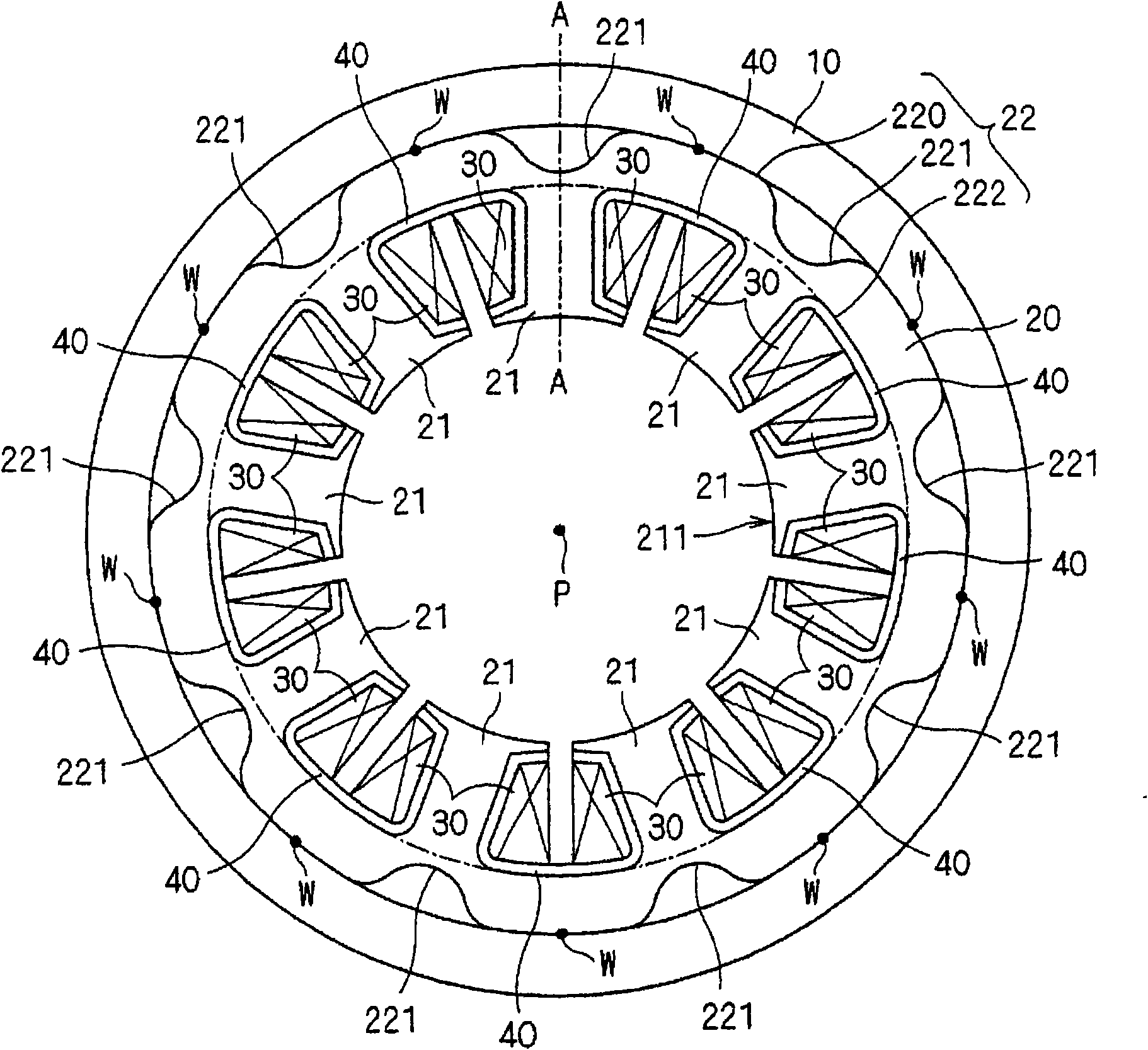
[0033] A rotating electric machine according to an embodiment of the present invention will be described. figure 1 is a schematic configuration diagram of a rotating electrical machine in a cross section perpendicular to the rotation axis P. FIG.

[0034] This rotating electric machine 1 has a case 10 , a stator core 20 , a coil 30 , and an insulating film 40 .

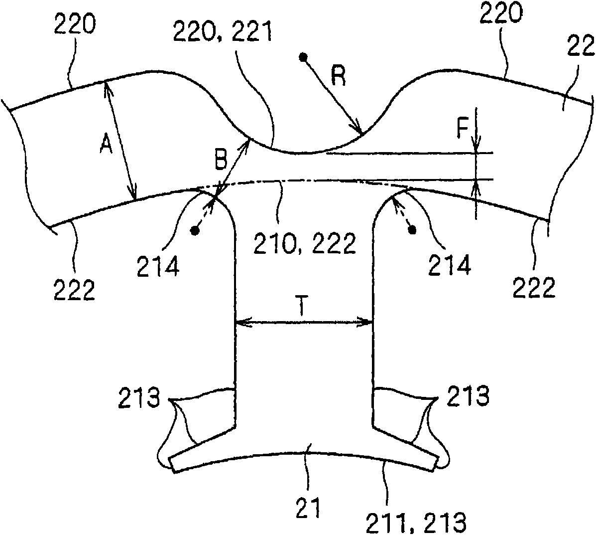
[0035] The stator core 20 has a plurality of teeth 21 and a back yoke 22 . The plurality of teeth 21 are arranged radially around the rotation axis P, and have one end on the opposite side of the rotation axis P in the radial direction around the rotation axis P. figure 1 In , nine teeth 21 are illustrated.

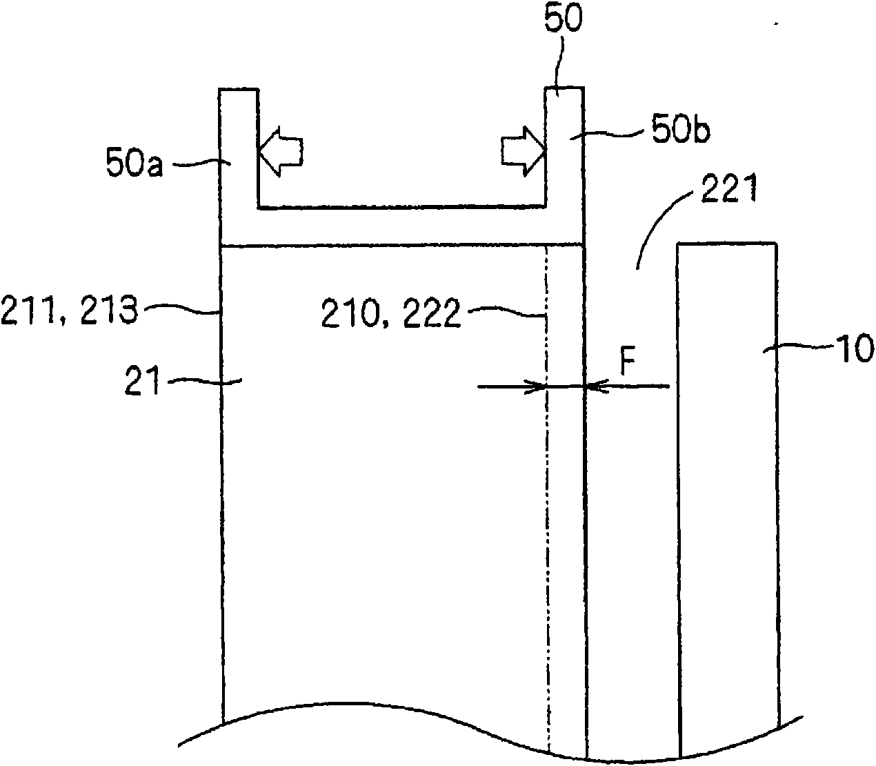
[0036] The back yoke 22 has an annular outer peripheral surface 220 and a cylindrical inner peripheral surface 222 connecting the one ends thereof. On the outer peripheral surface 220 , a plurality of recesses (hereinafter referred to as notches) 221 opening radially toward the opposite side of the rotation ax...


PUM


Abstract

A rotating electric machine in which, in welding a stator core and a case together, thermal damage to an insulation film due to the welding is suppressed. The rotating electric machine has the case (10) and the stator core (20). The stator core (20) has teeth (21) and a back yoke (22). Recesses (221) open to the side opposite a rotating shaft (P) are arranged in the outer peripheral surface (220)of the back yoke (22) such that each of the recesses (221) corresponds to each of the teeth (21). The case (10) and the stator core (20) are welded and fixed together at a position between each of tworecesses (221) adjacent to each other in the direction of a circumference about the rotating axis (P). The minimum distance between the root and recess (221) of each of the teeth (21) is smaller thanthe width in the radial direction of the back yoke.

Description

technical field [0001] The present invention relates to a rotating electrical machine and a compressor, and more particularly to a rotating electrical machine in which a coil is wound by concentrated winding. Background technique [0002] Patent Documents 1 to 3 disclose compressors in which a compression mechanism for compressing a refrigerant and a motor for driving the compression mechanism are integrally housed in a casing. In any one of Patent Documents 1 to 3, a notch is provided on the outer peripheral surface of the stator included in the motor, and the motor and the housing are shrink-fitted at the portion where the outer peripheral surface of the stator and the inner peripheral surface of the housing contact each other. etc fixed. The refrigerant is sent to the compression mechanism through the notch. Coils are wound around the teeth of the stator via an insulating film. [0003] Patent Document 1: Japanese Patent Laid-Open No. 2001-268824 [0004] Patent Docum...

Claims


Application Information

Patent Timeline
IPC IPC(8): H02K1/12H02K1/16F04B39/00
CPCH02K1/185H02K1/146F04B39/00H02K1/12H02K1/16
Inventor 安田善纪山际昭雄
Owner DAIKIN IND LTD
Why Eureka
Try Eureka