Backlight module and optical plate thereof

A technology of backlight module and optical board, applied in optics, optical components, nonlinear optics, etc., can solve the problems of increasing the number of light interfaces, reducing light utilization, and light loss.

Inactive Publication Date: 2010-02-17
HONG FU JIN PRECISION IND (SHENZHEN) CO LTD +1
View PDF0 Cites 6 Cited by
  • Summary
  • Abstract
  • Description
  • Claims
  • Application Information

AI Technical Summary

Problems solved by technology

[0005] However, when the light is transmitted in the prism sheet 10 and the upper diffusion sheet 14, part of the light will be absorbed and cause light loss; The number of interfaces increases the interface loss of light transmission and reduces light utilization

Method used


Image

  • Backlight module and optical plate thereof
  • Backlight module and optical plate thereof
  • Backlight module and optical plate thereof

Examples


Embodiment Construction

[0023] The backlight module and its optical board of the present invention will be further described in detail below with reference to the drawings and embodiments.

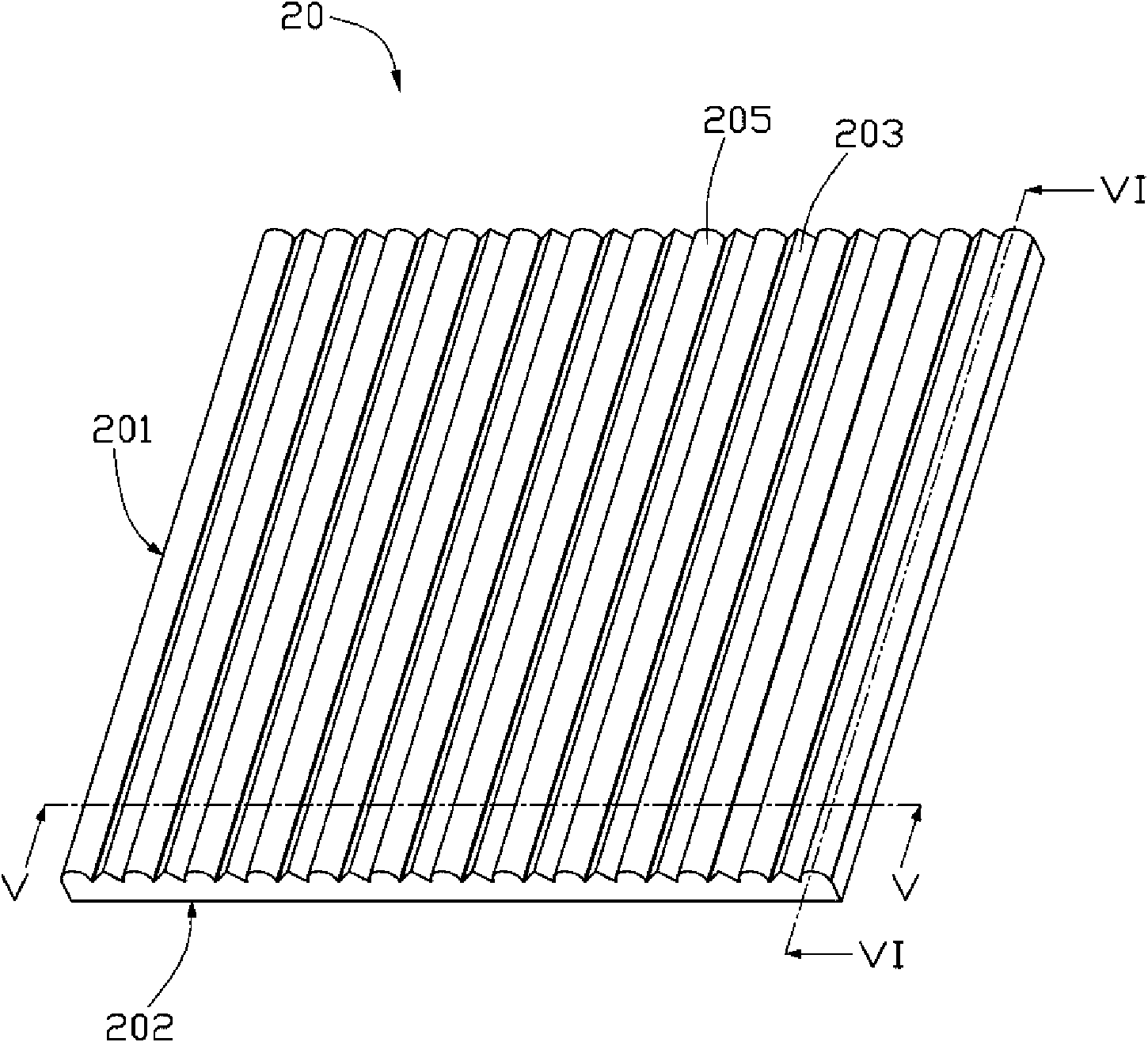
[0024] see Figure 3 to Figure 6 , the optical plate 20 according to the first embodiment of the present invention is made of a transparent material, and the optical plate 20 includes a first surface 201 and a second surface 202 opposite to the first surface 201 . The first surface 201 is formed with a plurality of elongated V-shaped protrusions 203 and elongated arc-shaped protrusions 205 arranged alternately and parallel to each other. The second surface 202 is formed with a plurality of spherical grooves 206 . In this embodiment, the vertical cross-sectional profile of the elongated arc-shaped protrusion 205 is a semi-circular arc.

[0025] The width of the elongated V-shaped protrusion 203 is marked as D, the vertex angle is marked as θ, and the height is marked as H1; then D, θ, H 1 Satisfy the following ...


PUM

PropertyMeasurementUnit
Top angleaaaaaaaaaa

Abstract

The invention provides a backlight module comprising a frame, a light source and an optical plate; the light source is arranged in the frame; the optical plate is arranged above the light source; theoptical plate is made of transparent material, comprises a first surface and a second surface opposite to the first surface, and also comprises a plurality of strip V-shaped bulges and a plurality ofstrip arc budges formed on the first surface as well as a plurality of spherical grooves formed on the second surface; and the strip V-shaped bulges and the strip arc budges formed on the first surface are arranged alternately in parallel; the invention also provides an optical plate applied by the backlight module; the backlight module has the advantage of improving effective light utilization rate and uniformity of light emission.

Description

technical field [0001] The invention relates to a backlight module and its optical board, in particular to a backlight module for liquid crystal display and its optical board. Background technique [0002] See figure 1 , shows a direct type backlight module 100, which includes a frame 11, a plurality of light sources 12 disposed inside the frame 11, and a diffusion plate 13 disposed above the light sources 12 and covering the frame 11. [0003] In use, the light generated by the plurality of light sources 12 can be diffused after entering the diffuser plate 13 . However, after being diffused by the diffuser plate 13, the angles at which light emerges from the diffuser plate 13 become more chaotic, so that its brightness in a specific viewing angle range is not high; It is still often difficult for the plate 13 to directly diffuse the light from the light source 12 evenly, so that the light emitted from the diffuser plate 13 is prone to light source afterimages, that is, ar...

Claims


Application Information

Patent Timeline
IPC IPC(8): G02F1/13357G02B6/00G02B1/04
Inventor 章绍汉
Owner HONG FU JIN PRECISION IND (SHENZHEN) CO LTD
Why Eureka
Try Eureka