
Patsnap Eureka
For R&D, Patsnap Eureka makes reading and utilizing patents & technical documents easy.
Patsnap Eureka AIR
Designed for self-driven R&D workflows. Generate viable solutions, solve complex R&D challenges, empower your innovation with AI.

Patsnap Eureka Materials
Designed for material experts only. Revolutionize your material R&D, from search, analyze, to developing new materials.

TechResearch
Generate reliable direction feasibility study reports for your R&D in just a few steps.

TechSeek
Discover and master advanced knowledge NOW. Basics, ideas, possibilities, all at once.

TechMind
As an expert in R&D Theories, TechMind can generates customized viable solutions instantly.

TechRisk
Analyze your overall solution with one click, know your potential R&D risks in advance.

TechMonitor
Get weekly tech updates, stay abreast of the latest tech innovations and key insights.
Concrete mixing drum
A mixing drum and concrete technology, which is applied to cement mixing devices, clay preparation devices, chemical instruments and methods, etc., can solve the problems of poor pumpability, easy layering and precipitation, uneven mixing of concrete, etc., and achieve low manufacturing cost, Not easy to stratify and precipitate, considerable economic benefits
- Summary
- Abstract
- Description
- Claims
- Application Information
AI Technical Summary
Problems solved by technology
Method used
Image

Examples
Embodiment 1
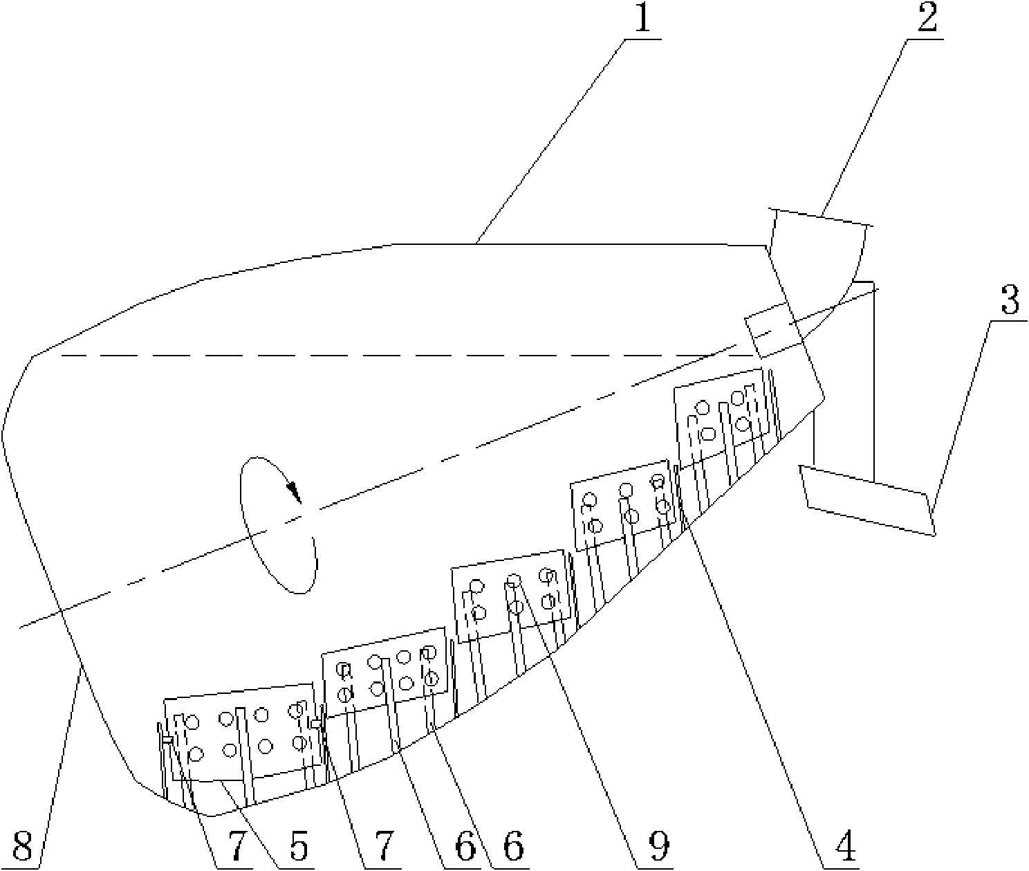
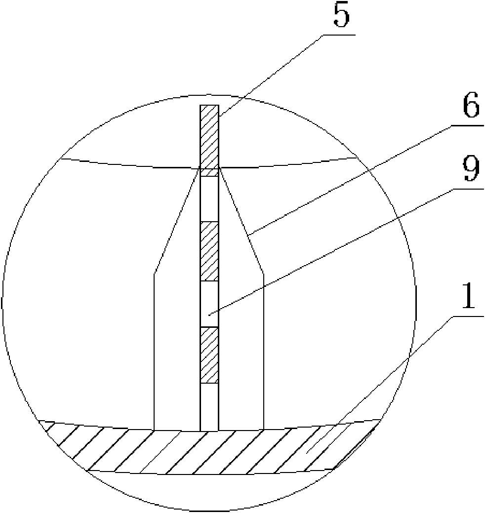
[0027] As attached to the manual Figure 1-4 As shown, a concrete mixing drum includes a cylinder body 1 and a material guide plate 4 distributed in a double helix. The material guide plate 4 is fixed on the inner wall of the cylinder body 1, and the height of the material guide plate 4 is between 400 and 500 mm. The two material guide plates 4 are curved surfaces, their roots are welded to the inner wall of the cylinder 1, and are distributed in a logarithmic helix in the cylinder 1, and the number thereof is determined according to the size of the mixing drum. At the mouth of the cylinder body 1, a section of feed guide cylinder is welded along the inner edges of the two spiral blades, and a feed inlet 2 is arranged on the guide cylinder. The opening of the barrel 1 is also provided with a discharge port 3 . In the interior of the cylinder 1, several stirring blades 5 are arranged along the axial direction of the cylinder 1, and the stirring blades 5 are fixed on the inner ...
Embodiment 2
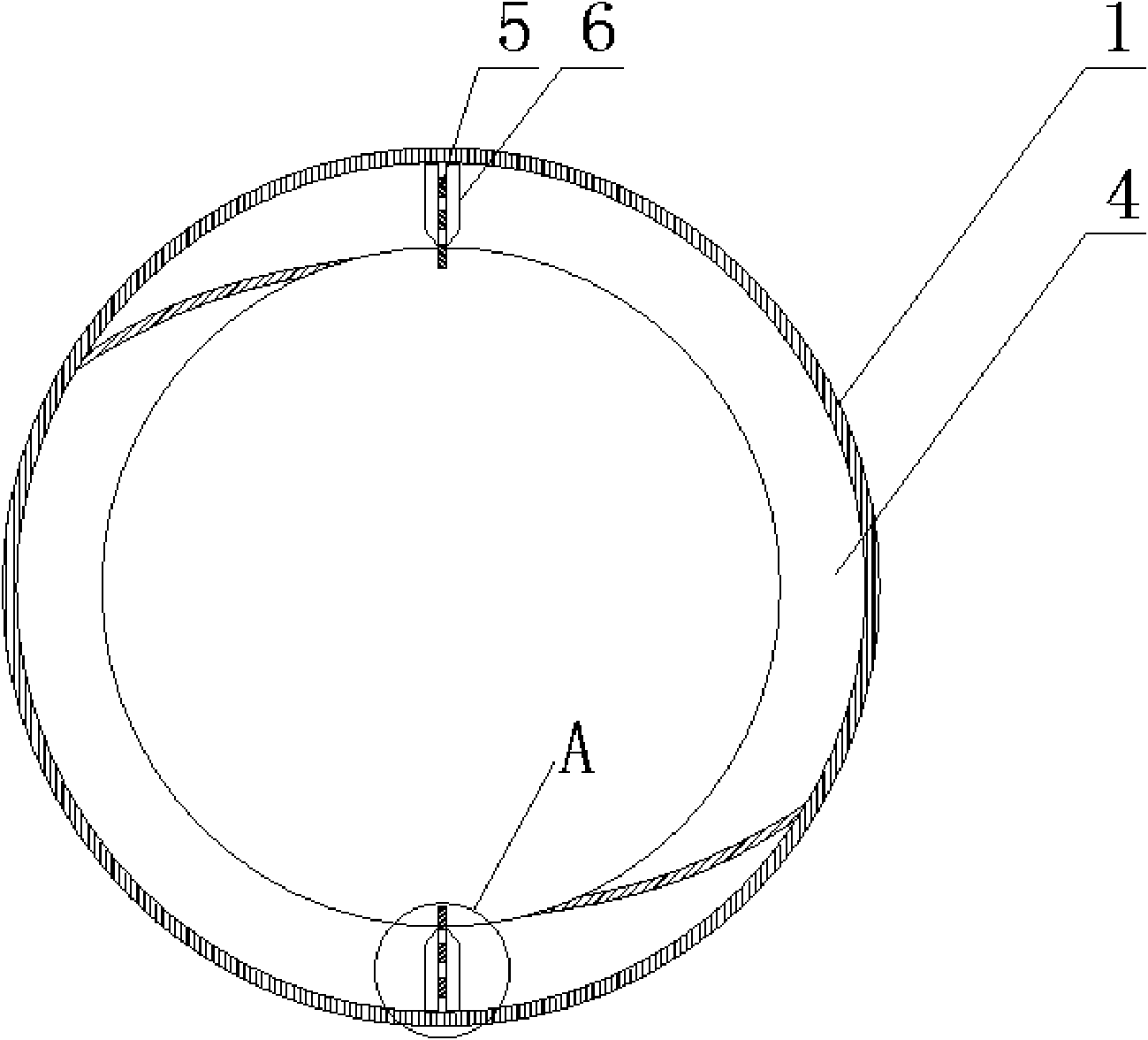
[0031] In this embodiment, on the basis of Example 1, when the bottom edge of the stirring sheet 5 is at the lowest point in the cylinder body 1, the angle between the bottom edge of the stirring sheet 5 and the horizontal direction is selected as less than or equal to 5 degrees; 8 The nearest two stirring pieces 5 are evenly distributed 3 in the circumferential direction of the inner wall of the cylinder body 1 (such as Figure 5 As shown), the total number of stirring pieces 5 inside the cylinder body 1 reaches 12, so as to achieve a better stirring effect.
[0032]Stirring piece 5 also can be evenly distributed 2-3 according to the diameter of cylinder body 1 on cylinder body 1 inner wall circumferential direction, makes the total number of cylinder body 1 internal stirring piece 5 be between 4-15, thus constitutes new implementation example.
Embodiment 3
[0034] This embodiment is the same as Embodiment 1, except that: the material guide plate 4 is distributed in the shape of an Archimedes spiral in the cylinder body 1 . Material guide plate 4 also can only be provided with one piece, thereby constitutes new embodiment.
PUM
| Property | Measurement | Unit |
|---|---|---|
| height | aaaaa | aaaaa |
Abstract
Description
Claims
Application Information
 - R&D Engineer
- R&D Manager
- IP Professional
- Industry Leading Data Capabilities
- Powerful AI technology
- Patent DNA Extraction
Browse by: Latest US Patents, China's latest patents, Technical Efficacy Thesaurus, Application Domain, Technology Topic, Popular Technical Reports.
© 2024 PatSnap. All rights reserved.Legal|Privacy policy|Modern Slavery Act Transparency Statement|Sitemap|About US| Contact US: help@patsnap.com