Aircraft with rear annular tail

A technology of empennage and aircraft, applied in the field of aircraft

Inactive Publication Date: 2010-02-10
AIRBUS OPERATIONS (SAS)
View PDF0 Cites 3 Cited by
  • Summary
  • Abstract
  • Description
  • Claims
  • Application Information

AI Technical Summary

Problems solved by technology

[0009] [09] In the existing aircraft, the aerodynamic surface of the empennage which is different from the basic shape is not the empennage shape respectively fixed to the fuselage, corresponding to the aircraft structure with the rear empennage, but the known T-shaped, The cruciform, H or V shape is still fairly close to the basic shape in its design without overall aerodynamic and structural optimization of the empennage assembly with the propulsion motor

Method used


Image

  • Aircraft with rear annular tail
  • Aircraft with rear annular tail
  • Aircraft with rear annular tail

Examples


Embodiment Construction

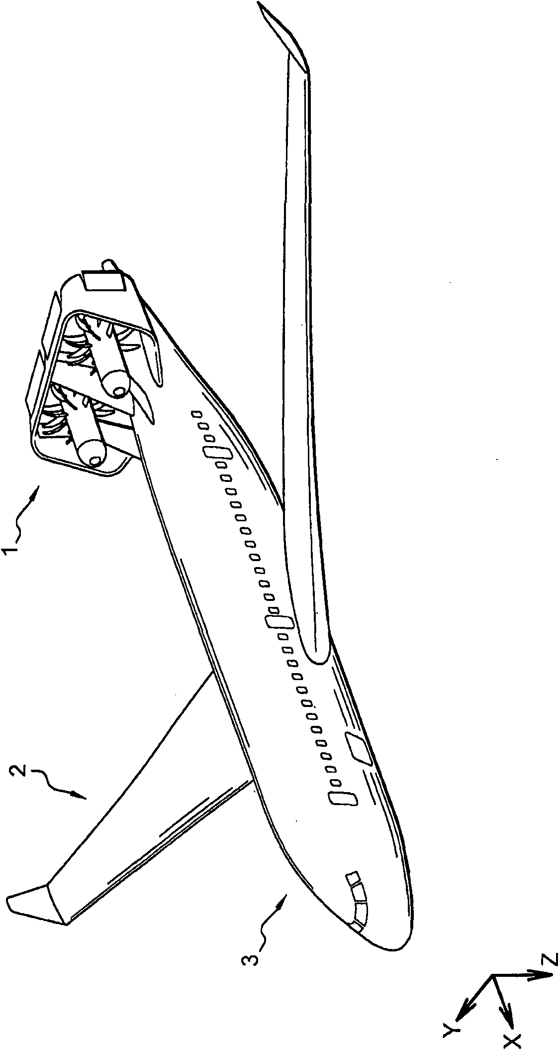
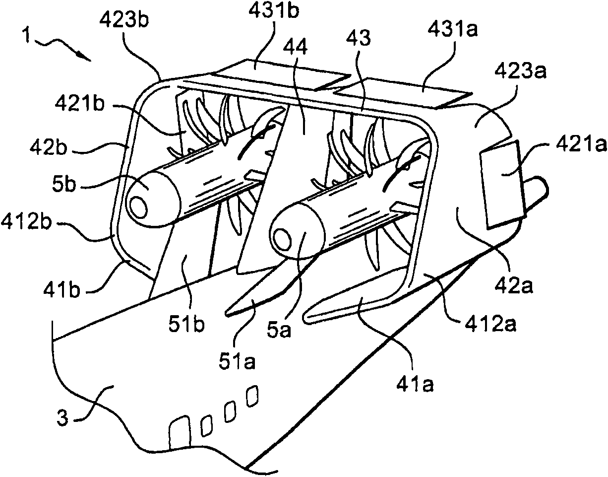
[0035] [35] figure 1 An example of a structure of an aircraft including a rear empennage assembly 1 according to the invention is shown.

[0036] [36] With respect to the rear empennage assembly, it is understood that it comprises a set of aerodynamic surfaces forming the empennage and situated aft of the wing 2 with respect to the longitudinal axis X of the aircraft in a direction substantially corresponding to The forward orientation of the moving direction of the aircraft in flight is positive.

[0037] [37] Here, the expression "aerodynamic surface" means a structure whose configuration is suitable for generating lifting aerodynamic forces, such as an aircraft wing, a horizontal stabilizer or an aircraft vertical stabilizer.

[0038] [38] The wing 2 and the empennage assembly 1 are generally fixed on the elongated aircraft fuselage 3 .

[0039] [39] Aircraft generally include a reference coordinate system consisting of a longitudinal axis X, a vertical axis Z, and an axi...


PUM


Abstract

The aircraft (1) has a wing and a horizontal upper aerodynamic surface (73), where the surface is situated at the rear of an aircraft. A jet engine (8a) is fixed under the horizontal upper aerodynamic surface by a pylon (9a), where the pylon has an upper part fixed to the surface and a lower part for maintaining the engine. A horizontal tail unit is fixed on a cylindrical shaped fuselage (2) in the rear of the wing. The tail unit is fixed to an upper part of a drift above the fuselage.

Description

technical field [0001] [01] The present invention is in the field of aircraft with rear propellers and rear empennage. Background technique [0002] [02] More particularly, the invention proposes a structure having an aircraft rear empennage assembly forming an annular structure closed in itself and associated with one or more propulsion engines also located in the tail section of the aircraft. [0003] [03] Transportation propelled by jet engines, or by turbine engines such as moteurs à hélices non carénées - the English term is Unducted Fan (unducted fan engine) or UDF - In aircraft, the rear empennage often includes, in the basic shape, a substantially vertical aerodynamic surface fixed to the fuselage in the tail section of the fuselage, i.e. the vertical empennage, and other substantially horizontal aerodynamic surfaces, i.e. the horizontal empennage; these aerodynamic surfaces ensure that the aircraft Stability in flight and allows the control of the aircraft by means...

Claims


Application Information

Patent Timeline
Patent Type & Authority Applications(China)
IPC IPC(8): B64C5/02B64C11/00B64C39/06B64D27/02
CPCY02T50/44B64D27/16B64C2039/105B64C5/02Y02T50/40
Inventor O·卡扎尔斯T·德吕奥
Owner AIRBUS OPERATIONS (SAS)
Why Eureka
Try Eureka