Capacitive acceleration sensor with acoustic cavity
An acceleration sensor, acceleration technology
- Summary
- Abstract
- Description
- Claims
- Application Information
AI Technical Summary
Problems solved by technology
Method used
Image
Examples
Embodiment 1
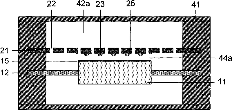
[0057] figure 1 It is a cross-sectional view of one of the embodiments of the capacitive acceleration sensor with an acoustic cavity of the present invention, which has a structure of a back plate. Such as figure 1 As shown, a capacitive acceleration sensor provided in this embodiment includes: an acceleration detection structure 10 composed of a proof mass 11 and an elastic vibrating membrane 12, and a back plate 21 with a damping hole 22 and a limit bump 23. , and the acceleration sensor frame 41.
[0058] In a plane perpendicular to the direction of motion, the detection mass 11 is located at the center of the sensor, and its boundary is connected to the inner boundary of the elastic vibrating membrane 12, and the elastic vibrating membrane 12 is located at the periphery of the detection mass 11, and its outer boundary is connected to the inner boundary of the sensor frame 41. The inner boundaries are connected. Both the detection mass 11 and the elastic vibrating membra...
Embodiment 2
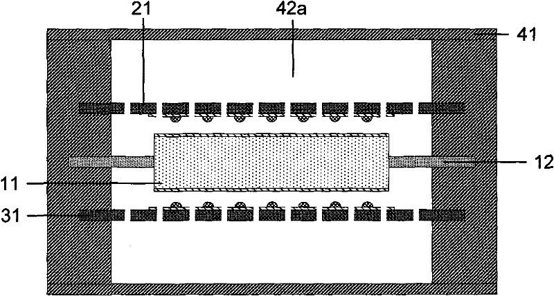
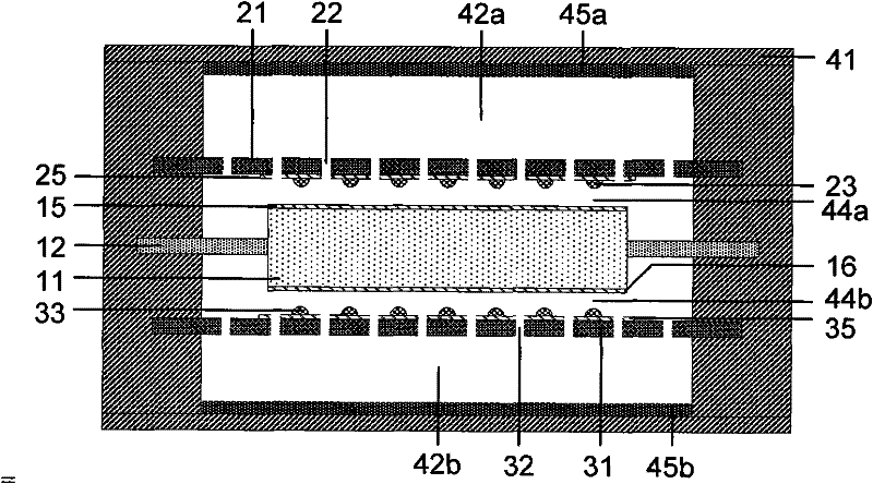
[0065] figure 2 It is a cross-sectional view of one of the embodiments of the capacitive acceleration sensor with an acoustic cavity of the present invention, which has a structure of two back plates. Such as figure 2 As shown, the capacitive acceleration sensor of this embodiment includes: an acceleration detection structure 10 composed of a proof mass 11 and an elastic diaphragm 12; two back plates 21 and 31; and an acceleration sensor frame 41 and other structures. Wherein, the mass block 11, the vibrating membrane 12, the back pole plate 21 and the back pole plate 31 are installed in the sensor frame 41, and the space between the upper and lower back pole plates 21 and the frame 41 formed after sealing The cavity and the cavity between the back plate 31 and the frame 41 are the acoustic cavity 42a and the acoustic cavity 42b.
[0066] In a plane perpendicular to the direction of motion, the detection mass 11 is located at the center of the sensor, and its boundary is c...
Embodiment 3
[0073] Figure 4 It is a sectional view of a damping hole structure on the mass block of one of the embodiments of the capacitive acceleration sensor with an acoustic cavity of the present invention. Such as Figure 4 As shown, the capacitive acceleration sensor provided in this embodiment includes: a detection mass 11 , an elastic diaphragm 12 , back plates 21 and 31 , and an acceleration sensor frame 41 .
[0074] In a plane perpendicular to the moving direction, the detection mass 11 and the elastic vibrating membrane 12 are both centrosymmetric figures, and both have the same center of symmetry. The detection mass 11 is located at the center of the sensor, and its boundary is connected to the inner boundary of the elastic diaphragm 12 , and the elastic diaphragm 12 is located at the periphery of the detection mass 11 , and its outer boundary is connected to the inner boundary of the sensor frame 41 .
[0075]In order to further reduce system damping and adjust system par...
PUM
 Abstract
Description
Claims
Application Information
 - R&D Engineer
- R&D Manager
- IP Professional
- Industry Leading Data Capabilities
- Powerful AI technology
- Patent DNA Extraction
Browse by: Latest US Patents, China's latest patents, Technical Efficacy Thesaurus, Application Domain, Technology Topic, Popular Technical Reports.
© 2024 PatSnap. All rights reserved.Legal|Privacy policy|Modern Slavery Act Transparency Statement|Sitemap|About US| Contact US: help@patsnap.com


