Eureka AIR delivers breakthrough ideas for toughest innovation challenges, trusted by R&D personnel around the world.

Manufacturing clamp for induction electric heater of liquid collection tank of gas-liquid separator

A technology of gas-liquid separation device and liquid collection tank, which is applied in the direction of lighting and heating equipment, refrigerators, refrigeration components, etc., and can solve the problems of limited heat exchange, damage to lubricating oil, small contact area between electric heater and liquid collection tank, etc. problems, to achieve the effect of convenient maintenance and replacement, enlarged contact area, uniform and effective heating

Inactive Publication Date: 2010-02-10
LG ELECTRONICS (TIANJIN) APPLIANCES CO LTD
View PDF7 Cites 6 Cited by
  • Summary
  • Abstract
  • Description
  • Claims
  • Application Information

AI Technical Summary

Problems solved by technology

[0009] However, there are many problems in the electric heater attached to the liquid collection tank of the above-mentioned prior art: the electric heater is disc-shaped, and is only suitable for collection tanks with a flat bottom. Liquid tank; the contact area between the electric heater and the liquid collection tank is small, and the heat exchange is limited; the electric heater installed at the bottom of the liquid collection tank may easily cause the temperature at the bottom of the liquid collection tank to be too high, damage the lubricating oil at the bottom, and affect The reliability of the air conditioner; moreover, there are certain difficulties in the installation and maintenance of the electric heater installed at the bottom of the liquid collection tank

Method used


Image

  • Manufacturing clamp for induction electric heater of liquid collection tank of gas-liquid separator
  • Manufacturing clamp for induction electric heater of liquid collection tank of gas-liquid separator
  • Manufacturing clamp for induction electric heater of liquid collection tank of gas-liquid separator

Examples


Embodiment Construction

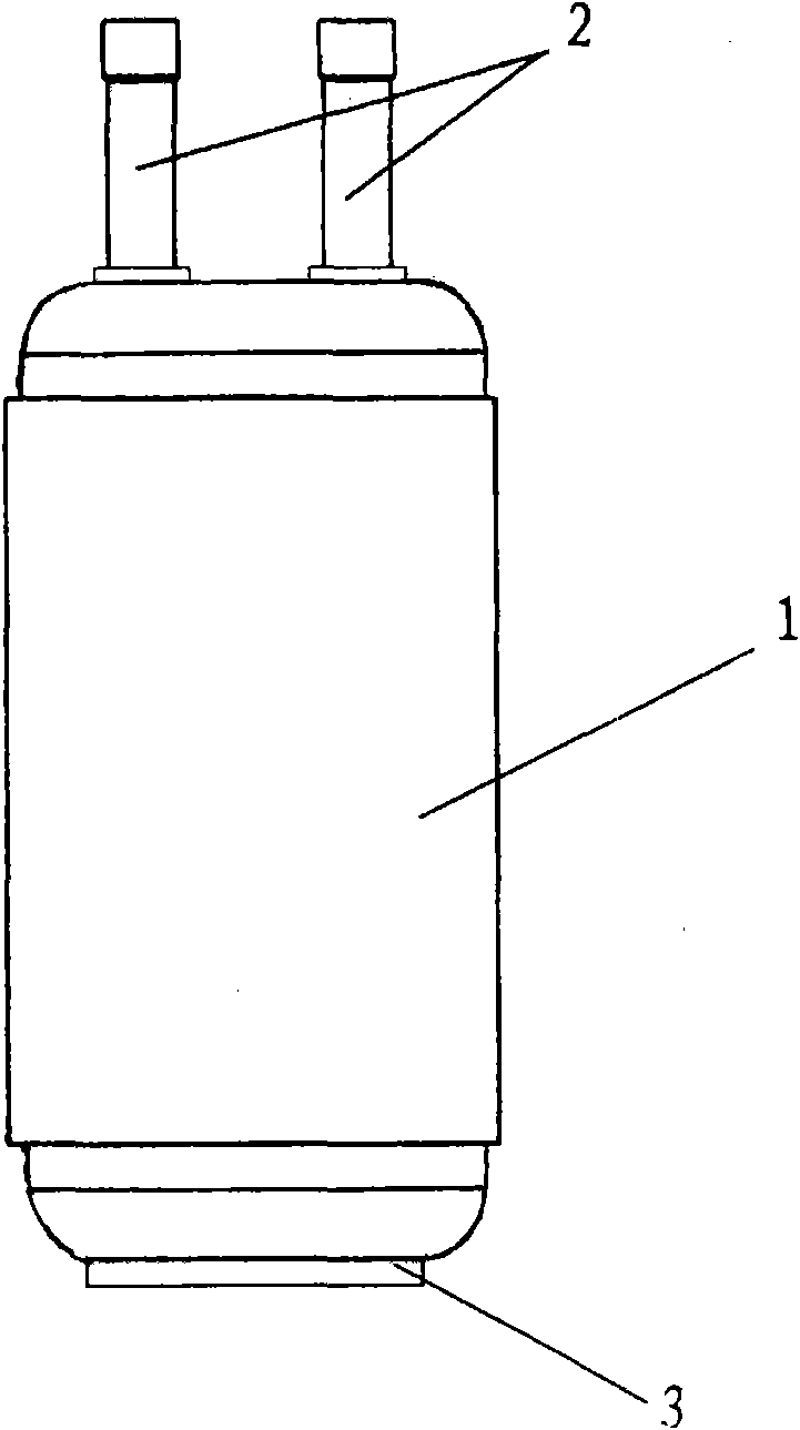
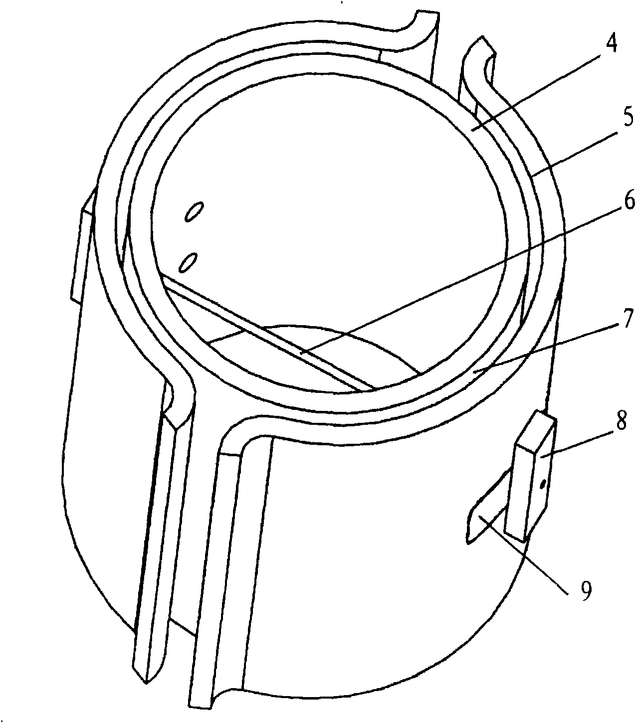
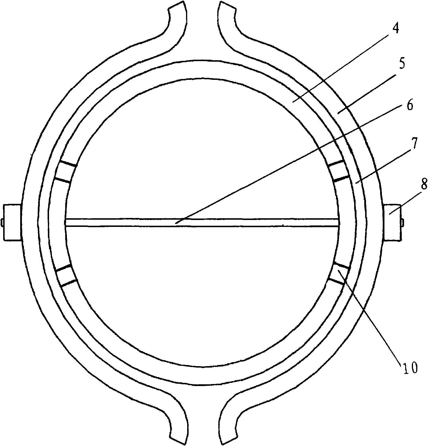
[0026] The production clamp for the induction electric heater of the liquid collection tank of the gas-liquid separation device of the present invention will be further described in conjunction with the accompanying drawings. figure 2 It shows the jig structure for making the induction electric heater of the gas-liquid separation device liquid collection tank of the present invention, image 3 A cross-sectional view showing the fabrication jig for an induction electric heater, Figure 4 It shows the state that the induction electric heater is installed on the liquid collection tank of the gas-liquid separation device.

[0027] As shown in the figure, the production jig for the induction electric heater of the liquid collection tank of the gas-liquid separation device involved in the present invention is composed of a cylindrical inner cylinder 4 and a curved surface shell 5, and two symmetrical curved surface shells 5 are fixed inside by metal threaded rods 6 On the outer si...


PUM


Abstract

The invention relates to a manufacturing clamp for induction electric heater, which consists of a cylindrical internal cylinder and curved surface shells. Two pieces of symmetrical curved surface shells are fixed on the outer side of the internal cylinder by a metal threaded rod, and arc-shaped gaps are reserved between the internal cylinder and the curved surface shells. A winding core of the electric heater is formed by winding a resistance wire in the gaps between the internal cylinder and the curved surface shells along the outer wall of the internal cylinder, and the wall of the internalcylinder is provided with four symmetrical threading holes used for selecting the starting position of winding the resistance wire randomly. A locking piece arranged outside the curved surface shellscan rotate at the end of the metal threaded rod, and the locking piece is rotated to separate the curved surface shells from the metal threaded, and to take the manufactured induction electric heaterdown. The induction electric heater consists of double-cambered-surface winding cores of the electric heater, is fixed on the outer side of a liquid collection tank through a clamp, and is suitable for the liquid collection tanks of all gas-liquid separators; besides, by enlarging the contact area of the electric heater and the liquid collection tank, the electric heater heats the gas-liquid separators more evenly and effectively; moreover, the electric heater is very convenient to mount, maintain and replace, and the reliability of an air container is improved.

Description

technical field [0001] The invention relates to an auxiliary part of an air conditioner, in particular to a manufacturing tool for an electric heater arranged on a liquid storage tank of a gas-liquid separation device of the air conditioner. Background technique [0002] The air conditioner uses the refrigerant circulating in its refrigeration system to exchange heat with the air flowing in the room to cool or heat up the room and provide people with a comfortable living and working environment. The refrigeration system of an air conditioner is mainly composed of a heat exchanger as an evaporator or condenser, a compressor, and a throttling device. In summer, the refrigerant in the refrigeration system performs a refrigeration cycle in the order of evaporation→compression→condensation→expansion to realize the cooling operation of the air conditioner; Run hot. [0003] The compressor is the main component of the refrigeration system of the air conditioner, which ensures the...

Claims


Application Information

Patent Timeline
Patent Type & Authority Applications(China)
IPC IPC(8): F25B43/00F22B3/02
Inventor 林密
Owner LG ELECTRONICS (TIANJIN) APPLIANCES CO LTD
Why Eureka
Eureka Blog
Learn More