
Supply pipeline of developing solution

A developer and supply tube technology, which is applied in the manufacture of circuits, electrical components, semiconductor/solid-state devices, etc., can solve the problems of crystal blockage, defectiveness, and reduced development of the developer nozzle, and achieve the effect of avoiding insufficient developing ability.

Inactive Publication Date: 2010-02-03
HEJIAN TECH SUZHOU
View PDF0 Cites 6 Cited by
  • Summary
  • Abstract
  • Description
  • Claims
  • Application Information

AI Technical Summary

Problems solved by technology

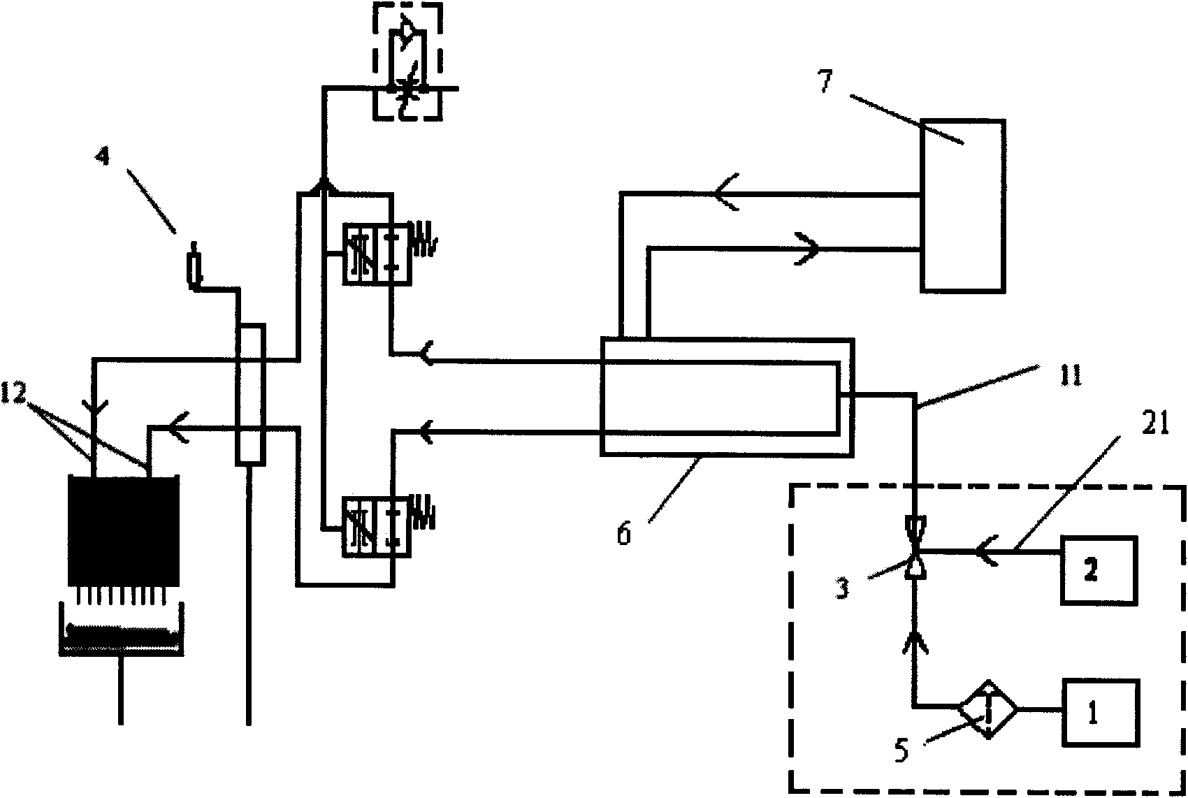
[0004] Aiming at the problem of crystallization blockage of developer nozzles in the prior art, the purpose of the present invention is to propose a developer supply pipeline. On the basis of the original developer supply pipeline, a deionized water pipeline for cleaning the developer nozzle is added. , to discharge the crystals existing in the nozzle, and clean the deposits in the pipeline, thereby reducing the chance of poor development

Method used


Image

  • Supply pipeline of developing solution
  • Supply pipeline of developing solution
  • Supply pipeline of developing solution

Examples


Embodiment Construction

[0015] The specific embodiment of the present invention will be described in more detail below in conjunction with the accompanying drawings.

[0016] see figure 2 , a developer supply pipeline, comprising a developer pipeline 11, a developer nozzle 12 positioned at the front end of the developer pipeline, and a deionized water pipeline 21 connected in parallel with the developer pipeline, the deionized water pipeline 21 passing through The control valve 3 installed to the developer pipeline is connected to the developer pipeline 11 . The developer pipeline generally has a buffer tank (Buffer tank, used for temporary storage of the developer), a Teflon pipeline, a filter (Filter, used for filtering the developer), and a fan (Fan flow, used for flow detection) , pneumatic valve (for controlling the switch of developing solution spraying), constant temperature exchange system 6, temperature monitor 7, nozzle 12 (for spraying developing solution onto the wafer surface) and othe...


PUM


Abstract

The invention relates to a supply pipeline of developing solution, comprising developing solution pipelines, developing solution nozzle arranged at front end of the developing solution pipelines, anda de-ionized water pipeline parallel with the developing solution pipelines; the de-ionized water pipeline is connected to the developing solution pipelines by being mounted to a control valve of thedeveloping solution pipelines. By adopting the structure of the invention, crystallized substance in the nozzle can be discharged, and the deposit in the pipelines can be cleared up, thus reducing opportunities of poor development.

Description

technical field [0001] The invention relates to a semiconductor development process, in particular to a developing solution supply pipeline. Background technique [0002] Such as figure 1 As shown, the traditional developer solution supply pipeline includes a developer solution pipeline 11, a constant temperature exchange system 6, a temperature monitor 7, a temperature controller 4, a developer solution nozzle and other devices. In the traditional developing unit, because the nozzle diameter (0.4mm) of E2 / E3 is very small, and the developer is easy to produce carbonate crystallization after combining with the air, it is easy to cause the nozzle to be blocked, so that the developer cannot be uniformly discharged from the nozzle. Distributed on the wafer, resulting in poor development of the wafer or crystals on the nozzle falling onto the wafer, resulting in product scrapping. [0003] Simultaneously, because the traditional developing solution supply pipeline does not pro...

Claims


Application Information

Patent Timeline
Patent Type & Authority Applications(China)
IPC IPC(8): G03F7/32H01L21/00
Inventor 鲁旭光胡清强陈晓琪
Owner HEJIAN TECH SUZHOU
Learn More