
Sheet folding machine

A technology for folding machines and sheets, applied in the fields of folding machines and knife holders, which can solve the problems of inaccessibility, space occupation, and inaccessibility of the knife shaft, and achieve easy assembly and disassembly, reduced assembly and adjustment time, and easy assembly and disassembly fast effect

Inactive Publication Date: 2010-02-03
HEIDELBERGER DRUCKMASCHINEN AG
View PDF6 Cites 2 Cited by
  • Summary
  • Abstract
  • Description
  • Claims
  • Application Information

AI Technical Summary

Problems solved by technology

The problem arises in this case that due to the arrangement of the knife folders at right angles to one another, the rear folding rollers and / or knife shafts of the fence folder are difficult to access
But this has the disadvantage that the knife shafts are still difficult to access, especially if the knife shafts are arranged behind the second knife folding mechanism
But this has a disadvantage on the one hand: the solution is very space-consuming in the drawn state
These work processes are time-consuming and adversely affect the resetting time

Method used


Image

  • Sheet folding machine
  • Sheet folding machine
  • Sheet folding machine

Examples


Embodiment Construction

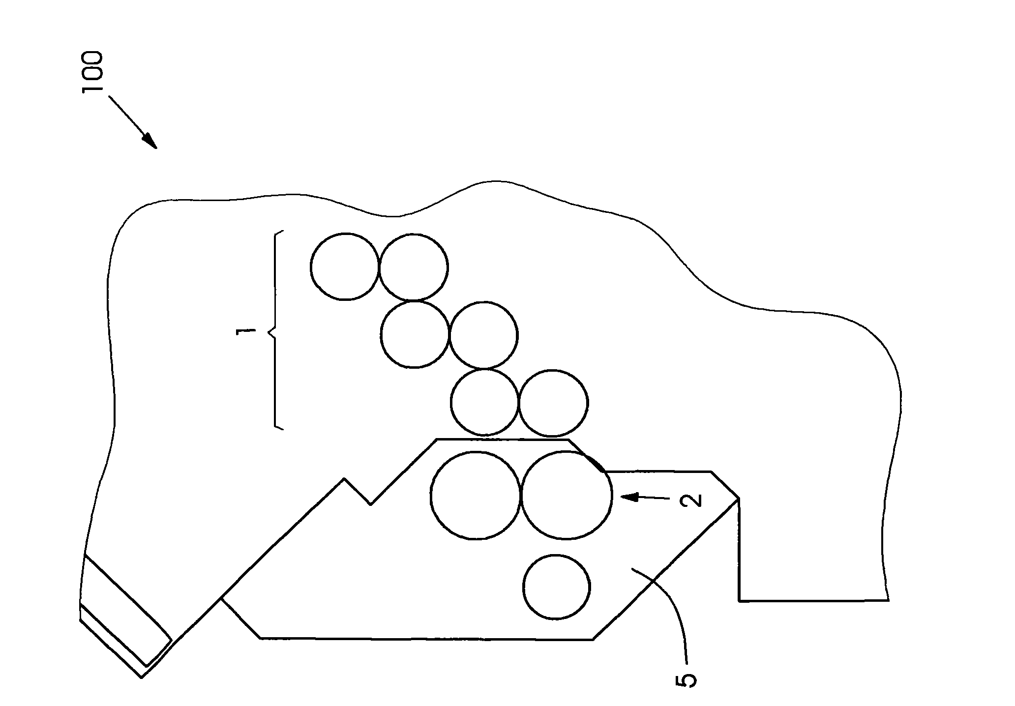
[0049] Folding machine 100's in figure 1 The exemplary embodiment schematically described in the figure relates to a fence folder for folding by means of a folding roller device 1 and a folding fence not shown here assigned to the folding roller device. Create multiple folded signatures. In this regard, several folding mechanisms are provided. Behind the last of these folding mechanisms is a pair of knife shafts 2 , which are mounted in separate roller housings 5 ​​.

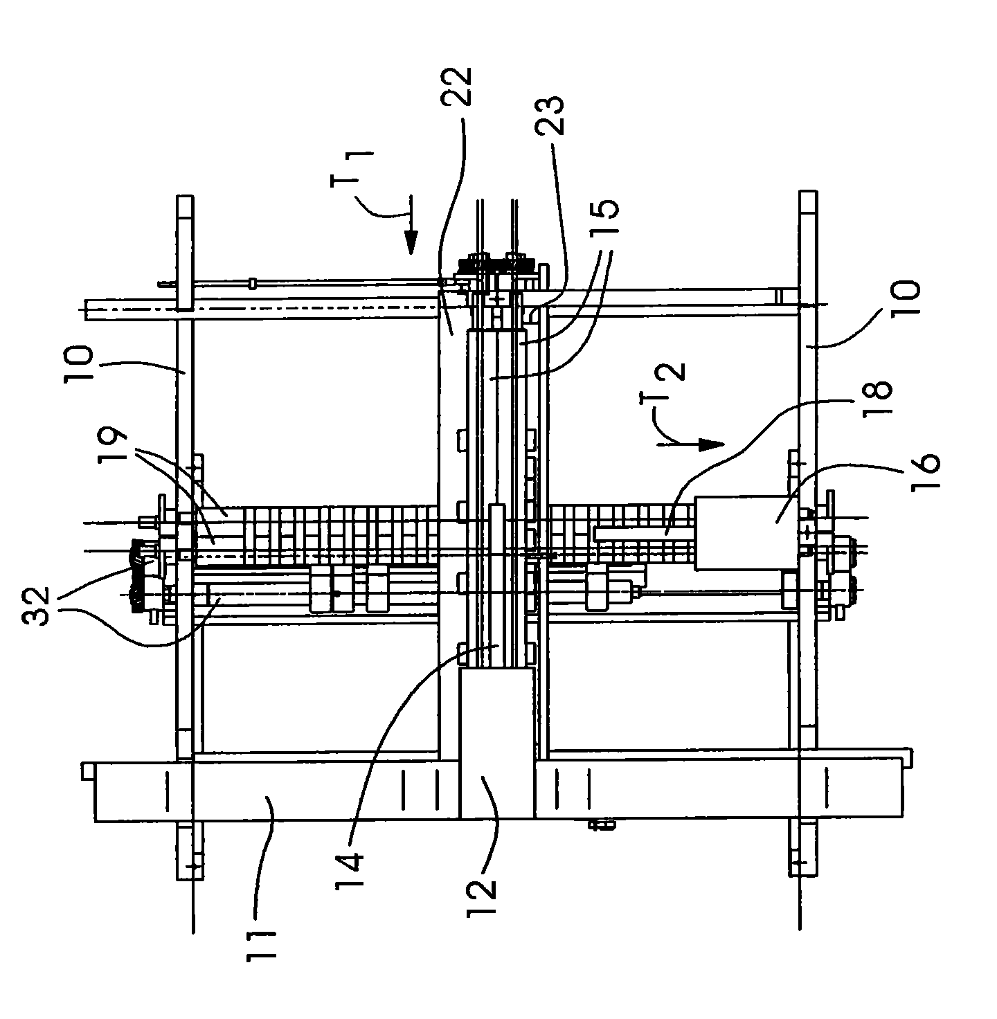
[0050] figure 2 A schematic plan view of the region of the knife folding mechanism of a preferred embodiment of the folding machine 100 according to the invention is shown. The knife folding mechanisms 12 , 14 , 15 , 16 , 18 , 19 themselves are also only shown schematically. exist figure 2 It can be seen in the folder 100 that two side walls 10 are spaced relatively parallel to each other, and these side walls are mainly connected to each other by a third side wall 11, wherein the third side wall 11 is re...


PUM


Abstract

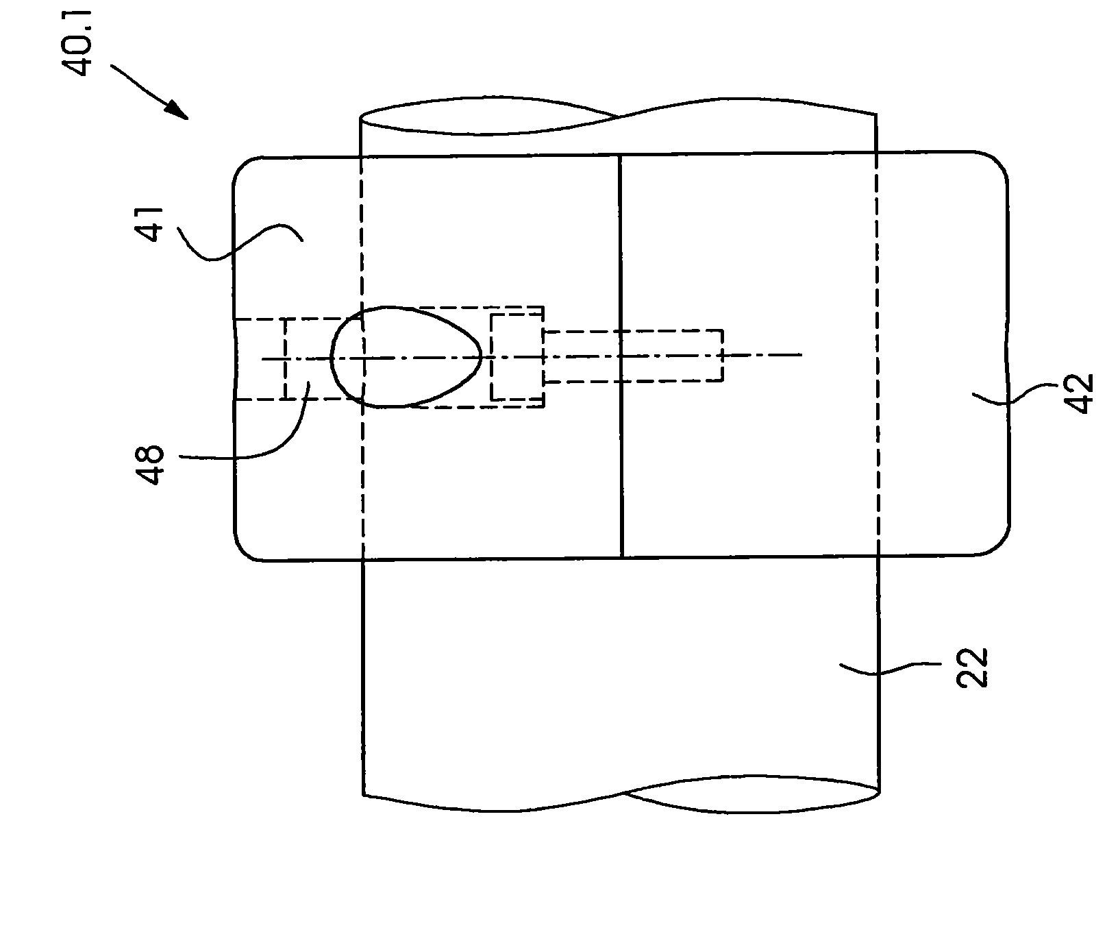
The present invention relates to a folding machine for folding sheets of paper, board and the like, includes at least one knife-shaft unit (2, 22, 23, 32) for cutting, perforating, scoring or crimping the sheets. The knife-shaft unit (2, 22, 23, 32) has at least one pair of driven knife shafts (22, 23). Knife-retaining units (40.3) for retaining knives (44) are fitted in a rotationally fixed manner on the knife shafts (22, 23). The knife-retaining units (40.3) have a split construction and are formed by a plurality of partial shells (41, 42).

Description

technical field [0001] The invention relates to a folding machine and a knife rest. Background technique [0002] Folding machines of this type are known from the prior art under the name hybrid folding machines. In this hybrid grid-knife folder, the parallel creases are folded on the grid-folding principle in the first folding station, while the subsequent cross-folding creases are each performed with vertically working folding knives. In this case, creases are generated perpendicular to the direction of transport of the folded sheet when entering the fence folding mechanism by the fence folding principle, while creases are produced by the knife folding principle relative to the direction of transport of the folded sheet when entering the fence folding mechanism. Creases parallel to the conveying direction when in the knife folding mechanism. [0003] The folding knife pushes the folded sheet down between two folding rollers, which grab and fold the sheet. Among the diff...

Claims


Application Information

Patent Timeline
Patent Type & Authority Applications(China)
IPC IPC(8): B65H45/12B65H45/14B65H45/28B31B50/56
CPCB65H2404/1141B65H45/30B65H35/02B65H2404/1415
Inventor H·阿克曼J·屈布勒
Owner HEIDELBERGER DRUCKMASCHINEN AG
Learn More