Sieve mesh with adjustable sieve pore gaps

A technology of gaps and sieve holes, which is applied in the direction of sieving, solid separation, grille, etc., can solve the problems of increasing economic burden, low screening efficiency, and low screening precision, so as to reduce economic burden, reduce economic expenditure, and screen The effect of high precision

Inactive Publication Date: 2010-02-03
庞红顺
View PDF0 Cites 16 Cited by
  • Summary
  • Abstract
  • Description
  • Claims
  • Application Information

AI Technical Summary

Problems solved by technology

The size of the sieve mesh depends on the size of the sieve hole. Since it is impossible to make all sizes into a sieve mesh, in order to facilitate production and manufacturing, the screening industry has formulated a series of specifications with the jump value as the sieve hole, and only produces sieves of corresponding specifications. Therefore, the existing sieves have the following disadvantages in use: 1. If the particle size of the material to be sieved does not belong to the standard size, you can only choose a sieve with a similar sieve size, resulting in screening accuracy Low; 2. When there is a special requirement for the size of the sieve hole, the screen has to be specially customized, which will easily cause time delay and economic waste; 3. If it is necessary to screen a variety of materials with different particle sizes, it is necessary to prepare multiple screens with different specifications. The type of screen mesh not only increases the economic burden, but also causes inconvenience to users, resulting in low screening efficiency

Method used


Image

  • Sieve mesh with adjustable sieve pore gaps
  • Sieve mesh with adjustable sieve pore gaps
  • Sieve mesh with adjustable sieve pore gaps

Examples


Embodiment Construction

[0025] The present invention will be further described in detail below through the specific examples, the following examples are only descriptive, not restrictive, and cannot limit the protection scope of the present invention with this.

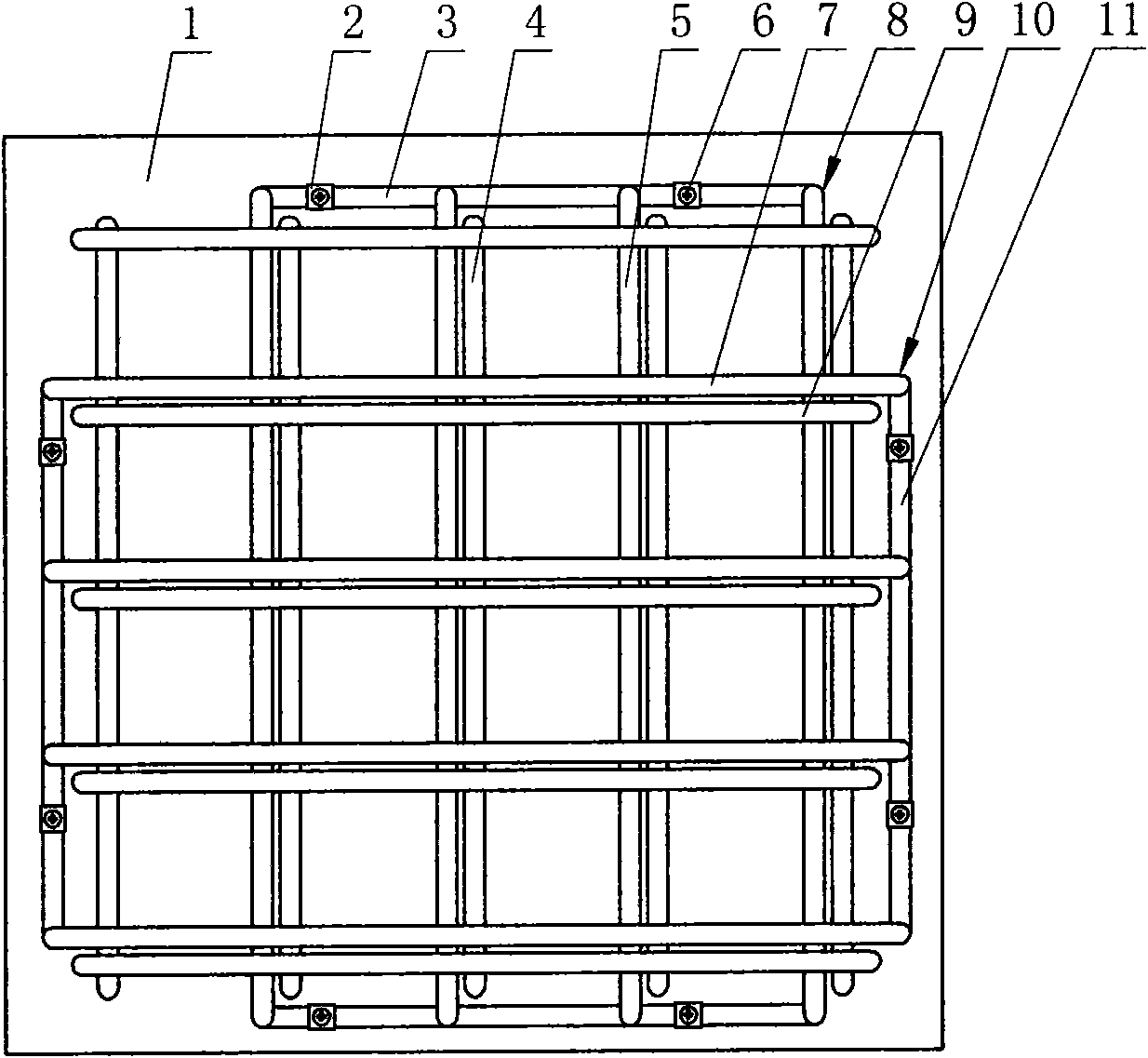
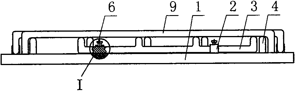
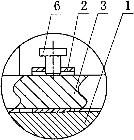
[0026] A sieve cloth with adjustable clearance between sieve holes is composed of a frame 1, cross bars 9 and longitudinal bars 4, and the cross bars and longitudinal bars are evenly distributed and interlacedly installed on the frame to form sieve holes.

[0027] The innovation of the present invention is that: a group of movable frames 8 moving along the X axis and a group of movable frames 10 moving along the Y axis are arranged on the frame, and the movable frames moving along the X axis and the movable frames moving along the Y axis are both 1 to 10. figure 1 and Figure 5 Schematic diagrams for one group and two groups of active frames are shown respectively.

[0028] The upper beams 5 uniformly distributed by each movable frame movi...


PUM


Abstract

The invention relates to a sieve mesh with adjustable sieve pore gaps. An edge frame is provided with a group of movable frames moving along an X shaft and a group of movable frames moving along a Y shaft; an upper beam which is uniformly distributed and made by each movable frame moving along the X shaft is respectively positioned between adjacent longitudinal rods, is parallel to the longitudinal rods and positioned in the same plane, and a lower beam of the movable frame slides in a guiding manner by a guide sleeve fixedly arranged on the edge frame; and an upper beam which is uniformly distributed and made by each movable frame moving along the Y shaft is respectively positioned between adjacent horizontal rods, is parallel to the horizontal rods and positioned in the same plane, and alower beam of the movable frame slides in a guiding manner by a guide sleeve fixedly arranged on the edge frame. The sieve mesh has reasonable design, convenient use, high sieving precision and highefficiency, is economical and practical, and can adjust the size of the sieve pore continuously; and the sieve mesh can adjust the size of the sieve pore in a certain range, is not limited by the specification when in use and can realize the multiuse effect with one mesh.

Description

technical field [0001] The invention relates to the field of sieving and filtering, in particular to a sieve cloth with adjustable sieve gap. Background technique [0002] In mineral processing, construction, chemical industry and other industries, filter screens are often used to separate materials of different particle sizes. Existing sieves usually consist of a frame and horizontal bars and vertical bars installed on the frame, and the horizontal bars and vertical bars are arranged in a criss-cross pattern to form screen holes. When screening, different specifications of screens can be selected for screening according to the particle size of the materials to be separated. The size of the sieve mesh depends on the size of the sieve hole. Since it is impossible to make all sizes into a sieve mesh, in order to facilitate production and manufacturing, the screening industry has formulated a series of specifications with the jump value as the sieve hole, and only produces sie...

Claims


Application Information

Patent Timeline
Patent Type & Authority Applications(China)
IPC IPC(8): B07B1/46
Inventor 庞红顺王翠苹
Owner 庞红顺
Why Eureka
Try Eureka