T-shaped linear ultrasonic motor oscillator
A linear ultrasonic motor and vibrator technology, which is applied in the directions of generators/motors, electrical components, piezoelectric effect/electrostrictive or magnetostrictive motors, etc., can solve the problem of low electromechanical coupling efficiency and mechanical output capability of piezoelectric ultrasonic motors. Constraints, poor mechanical output capability, etc., to achieve the effect of simple structure, high electromechanical coupling efficiency, and improved amplitude and vibration speed
- Summary
- Abstract
- Description
- Claims
- Application Information
AI Technical Summary
Problems solved by technology
Method used
Image
Examples
specific Embodiment approach 1
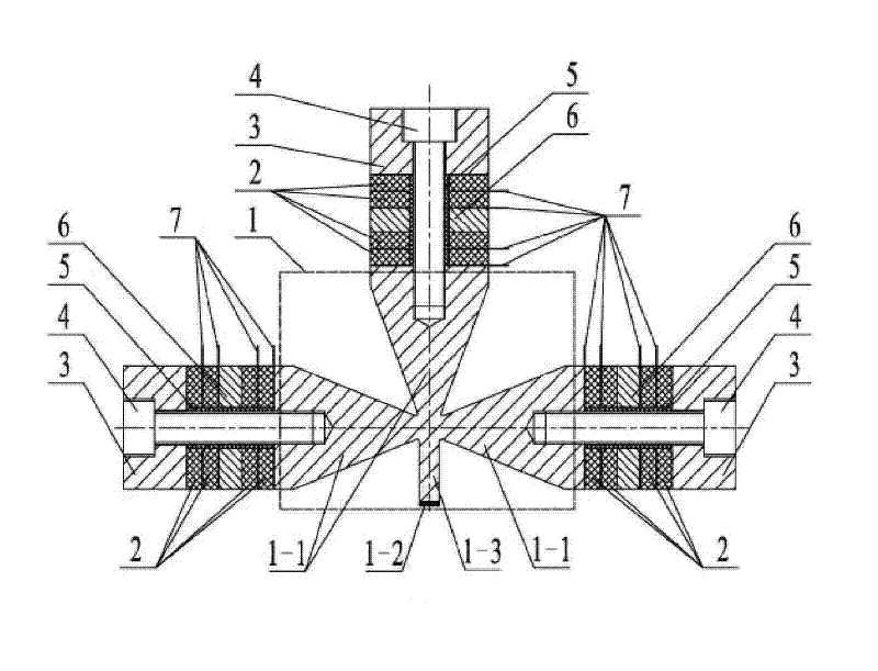
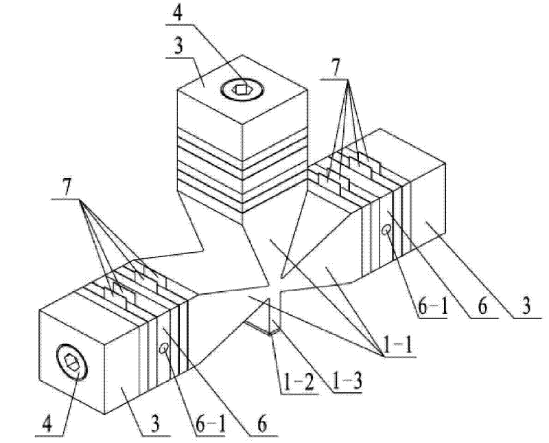
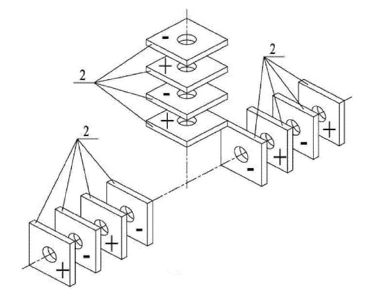
[0010] Specific implementation mode one: combine Figure 1 to Figure 4 Describe this embodiment, which includes a T-shaped front end cover 1, six pairs of piezoelectric ceramic sheets 2, three rear end covers 3, three fastening screws 4, three insulating sleeves 5, three flanges 6 and ten Two electrode sheets 7; it is characterized in that the T-shaped front end cover 1 includes three horns 1-1, a driving foot 1-3 and a wear-resistant liner 1-2; the horn 1-1 is a section It is a rectangular and gradually tapering quadrangular prism. The driving foot 1-3 is a cuboid. The small ends of the three horns 1-1 are integrally connected and arranged in a T shape. One end surface of the driving foot 1-3 is connected to three The position where the horns 1-1 are connected, and the center line of the driving foot 1-3 coincides with the center line of one of the horns 1-1, and the other two horns 1-1 are symmetrically arranged on the said The two sides of the center line are located on a ...
specific Embodiment approach 2
[0011] Specific implementation mode two: combination Figure 1 to Figure 3 This embodiment is described. The difference between this embodiment and the first embodiment is that the cross-sections of the piezoelectric ceramic sheet 2 and the rear end cover 3 are square or circular. Other compositions and connection methods are the same as those in Embodiment 1.
specific Embodiment approach 3
[0012] Specific implementation mode three: combination figure 2 This embodiment is described. The difference between this embodiment and the first or second embodiment is that a tapered positioning hole 6-1 is processed at the center of the side of the flange 6 . Other compositions and connection modes are the same as those in Embodiment 1 or 2. The tapered positioning hole 6-1 is used to support the vibrator and apply the pre-tightening force between the vibrator and the mover.
PUM
 Abstract
Description
Claims
Application Information
 - R&D
- Intellectual Property
- Life Sciences
- Materials
- Tech Scout
- Unparalleled Data Quality
- Higher Quality Content
- 60% Fewer Hallucinations
Browse by: Latest US Patents, China's latest patents, Technical Efficacy Thesaurus, Application Domain, Technology Topic, Popular Technical Reports.
© 2025 PatSnap. All rights reserved.Legal|Privacy policy|Modern Slavery Act Transparency Statement|Sitemap|About US| Contact US: help@patsnap.com


