Electric valve
An electric valve and valve port technology, which is applied to valve details, valve devices, engine components, etc., can solve problems such as workability problems, undisclosed stopper mechanisms, and difficulty in assembling threaded parts, achieving simple assembly operations and easy manufacturing. Effect
Active Publication Date: 2011-01-05
SAGINOMIYA SEISAKUSHO INC
View PDF2 Cites 5 Cited by
- Summary
- Abstract
- Description
- Claims
- Application Information
AI Technical Summary
Problems solved by technology
Therefore, when the valve holder 70 is screwed to the bushing 90 and assembled, the stopper portion (upper end abutment portion 110 ) that restricts the position of the upper end interferes with the rod 150 during assembly, making it very difficult to assemble the threaded portion. question
Furthermore, Patent Document 2 mainly discloses a manufacturing method of a stopper that stops the rotation of the rotor at the valve closing position by aligning the notch start position of the screw thread with the position of the protrusion of the stopper, and assembling as described above The stopper mechanism that restricts the upper end position when the valve is opened, which is particularly problematic in terms of workability, is not disclosed
Method used
View moreImage
Smart ImageViewing Examples
Examples
Embodiment Construction
Login to View More PUM
 Abstract
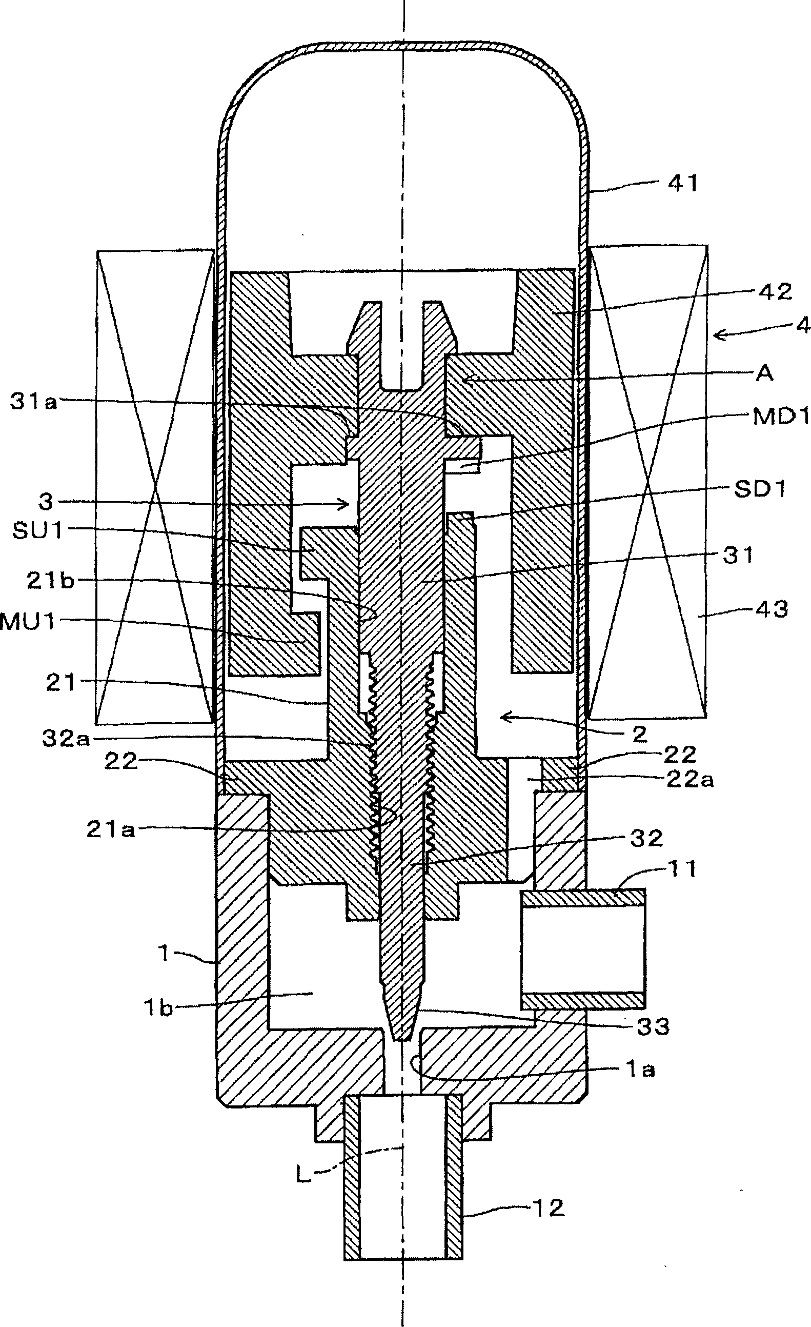
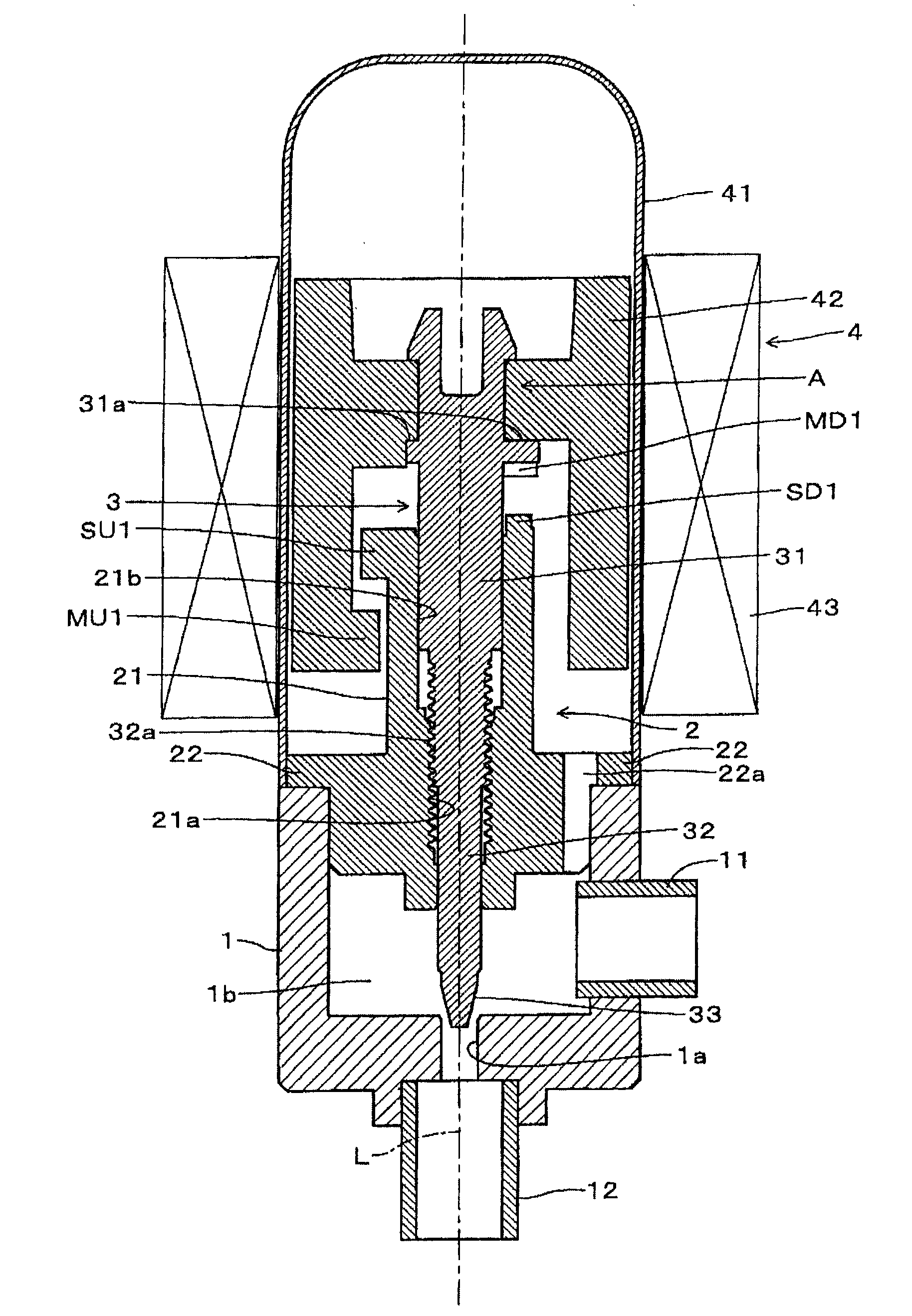
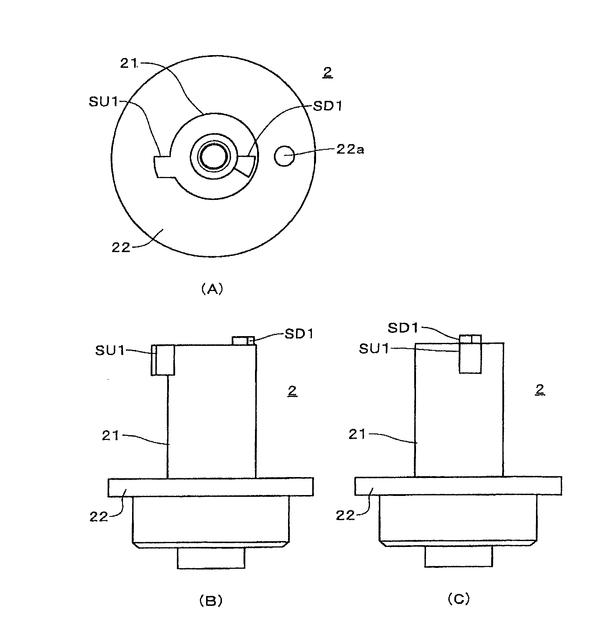
An electric valve is provided. A support component (2) is easily assembled by a rotor shaft (3) and a magnetic rotor (2); a rotor shaft and a magnetic rotor (42) are formed by different components; a lower fixed arrester (SD1) is formed at the end of the support component; an upper fixed arrester (SU1) is formed on the support component; a lower movable arrester (MD1) is formed on the rotor shaft; an upper movable arrester (MU1) is formed on the magnetic rotor; the support component, rotor shaft and magnetic rotor are made of resin; the external screw thread (32a) of the rotor shaft is twisted in the internal screw thread (21a) of the support component; the rotor shaft is arranged on the support component; at the noninterference position of the upper movable arrester and the upper fixed arrester, the magnetic rotor is embedded at the blocking part (A) of the rotor shaft to be fastened; one end of the magnetic rotor opposite to the needle part (33) can be embedded in the blocking part of the rotor shaft; or the rotor shaft and magnetic rotor are fastened by a mounting component.
Description
Electric valve technical field The present invention relates to an electric valve for controlling the flow rate of refrigerant, such as an expansion valve of a refrigeration cycle. Background technique Conventionally, in the refrigeration cycle, an expansion valve is installed between the outdoor heat exchanger and the indoor heat exchanger. In the cooling mode, the refrigerant from the outdoor heat exchanger is expanded by the expansion valve and guided to the indoor heat exchanger. ; In the heating mode, the refrigerant from the indoor heat exchanger is expanded by the expansion valve and then directed to the outdoor heat exchanger. As such an expansion valve, in order to cope with normal operation, defrosting operation, dehumidification operation, etc., various proposals have been made to control the flow rate of the refrigerant (see Patent Document 1 and Patent Document 2). Such an existing electric valve uses the motor to rotate the magnetic rotor and the rotor shaf...
Claims
Login to View More Application Information
Patent Timeline
 Patent Type & Authority Patents(China)
IPC IPC(8): F16K31/04F16K31/50
CPCY02B30/72
Inventor 中野诚一平川尚小野寺康明中川大树
Owner SAGINOMIYA SEISAKUSHO INC
Features
- R&D
- Intellectual Property
- Life Sciences
- Materials
- Tech Scout
- Unparalleled Data Quality
- Higher Quality Content
- 60% Fewer Hallucinations
Learn More Browse by: Latest US Patents, China's latest patents, Technical Efficacy Thesaurus, Application Domain, Technology Topic, Popular Technical Reports.
© 2025 PatSnap. All rights reserved.Legal|Privacy policy|Modern Slavery Act Transparency Statement|Sitemap|About US| Contact US: help@patsnap.com


