
LED light source module

A technology of LED light source and light-emitting module, which is applied in the direction of light source, electric light source, point light source, etc. It can solve the problems of complex assembly, large loss of luminous flux, and large structure of lamps, and achieve the effect of convenient use and simple structure

Inactive Publication Date: 2010-01-13
SUN YAT SEN UNIV
View PDF3 Cites 7 Cited by
  • Summary
  • Abstract
  • Description
  • Claims
  • Application Information

AI Technical Summary

Problems solved by technology

The secondary optical lens will also lead to a large structure of the lamp, which has the disadvantages of complex assembly and large loss of luminous flux

Method used


Image

  • LED light source module
  • LED light source module

Examples


Embodiment Construction

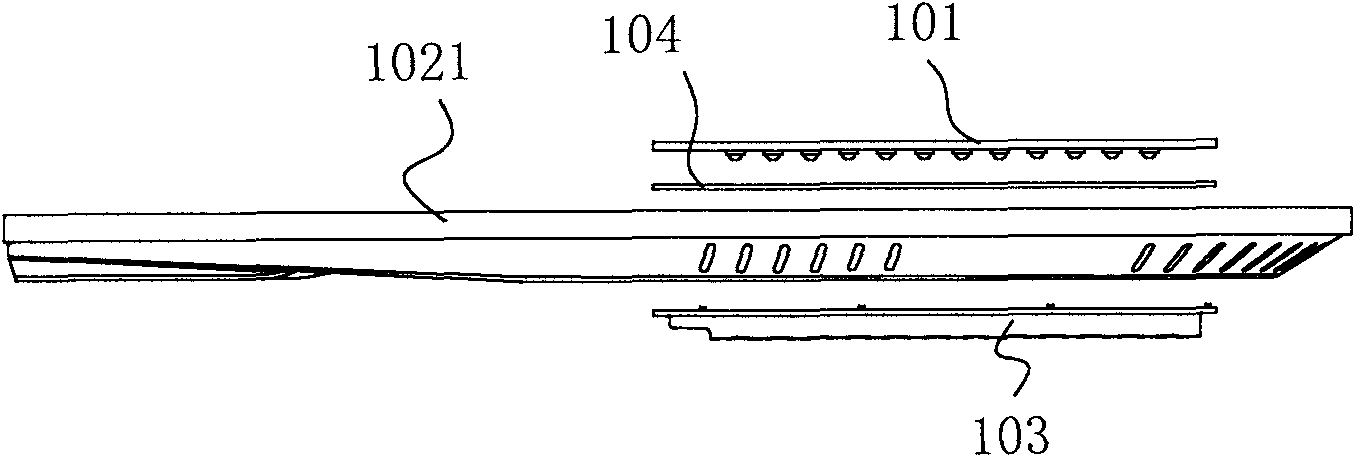
[0018] The present invention will be described in further detail below in conjunction with the accompanying drawings. refer to figure 1 , figure 2 , the first embodiment of the present invention is an LED light source module, including an LED lighting module 101 and a module base, the module base in this embodiment is the lamp body 102, and the lamp body 102 has an upper lamp body and a lower The lamp body 1021; the LED light source module also includes an optical cover plate 103, and the optical cover plate 103 is fixed on the module base. In this embodiment, it is arranged on the lower lamp body 1021. The module base, that is, the lamp body 102 defines a closed space, and the LED lighting module 101 is arranged in the closed space; the outer surface of the optical cover plate 103 is a plane, and the inner surface of the optical cover plate 103 has Several concave curved surfaces; in this embodiment, several concave curved surfaces and planes constitute several secondary o...


PUM


Abstract

The invention relates to an LED illumination device, in particular to an LED light source module comprising an LED light emitting module and a module base. The LED light source module is characterized by also comprising an optical cover plate which is fixedly arranged on the module base to define a closed space, wherein the LED light emitting module is arranged in the closed space; the outer surface of the optical cover plate is a plane or a smooth arc surface; the inner surface of the optical cover plate is provided with a plurality of inner sunken faces; the LED light emitting module is provided with a plurality of LED illuminants, an inner sunken face is correspondingly distributed at the front of each LED illuminant. The invention provides an LED light source module which is simple in structure and convenient to use.

Description

technical field [0001] The invention relates to an LED lighting device, in particular to an LED light source module. Background technique [0002] Compared with traditional street lights, LED street lights not only have the characteristics of good chromaticity, maintenance-free, and long life, but also are more energy-efficient than traditional street lights. [0003] Chinese utility model patent document CN201242086Y discloses a slot-type secondary optical lens that produces a rectangular spot. The slot-type secondary optical lens that produces a rectangular spot is a strip-shaped light-transmitting plate made of a light-transmitting material. A front transmission surface and a rear transmission surface are arranged on the strip, and the rear transmission surface includes a bottom projection surface parallel to the front transmission surface and a side reflection surface with an oblique angle to the front transmission surface, and a light source is formed on the main transm...

Claims


Application Information

Patent Timeline
Patent Type & Authority Applications(China)
IPC IPC(8): F21S2/00F21V5/00F21V5/08F21V17/00F21Y101/02F21K9/20F21Y115/10
Inventor 王钢冼钰伦祁山薛志强高艳春
Owner SUN YAT SEN UNIV
Learn More