
Paper money outlet door of electromagnetic valve

A technology of solenoid valve and banknote gate, which is applied in the direction of processing coins or valuable banknotes, devices and instruments for accepting coins, etc., can solve the problems of high cost, control error, troublesome assembly, etc., and achieves high control accuracy requirements and simple overall structure. , The effect of convenient installation and maintenance

Inactive Publication Date: 2010-01-06
GUANGZHOU KINGTELLER TECHNOLOGY CO LTD
View PDF0 Cites 5 Cited by
  • Summary
  • Abstract
  • Description
  • Claims
  • Application Information

AI Technical Summary

Problems solved by technology

[0002] The structure of the current cash-out door is relatively complicated, and it is more troublesome to assemble, which leads to a relatively high cost of putting into production. In addition, the driving mode of the current cash-out door is driven by a motor, which not only affects the rotation position of the motor The control accuracy requirements are very high, and it is very prone to failure. After the power is cut off, the self-locking cannot be restored, and after the motor has been used for a certain period of time, its control will also have errors, which will affect the normal operation of the banknote door.

Method used


Image

  • Paper money outlet door of electromagnetic valve
  • Paper money outlet door of electromagnetic valve
  • Paper money outlet door of electromagnetic valve

Examples


Embodiment Construction

[0019] The present invention will be further elaborated below in conjunction with the accompanying drawings.

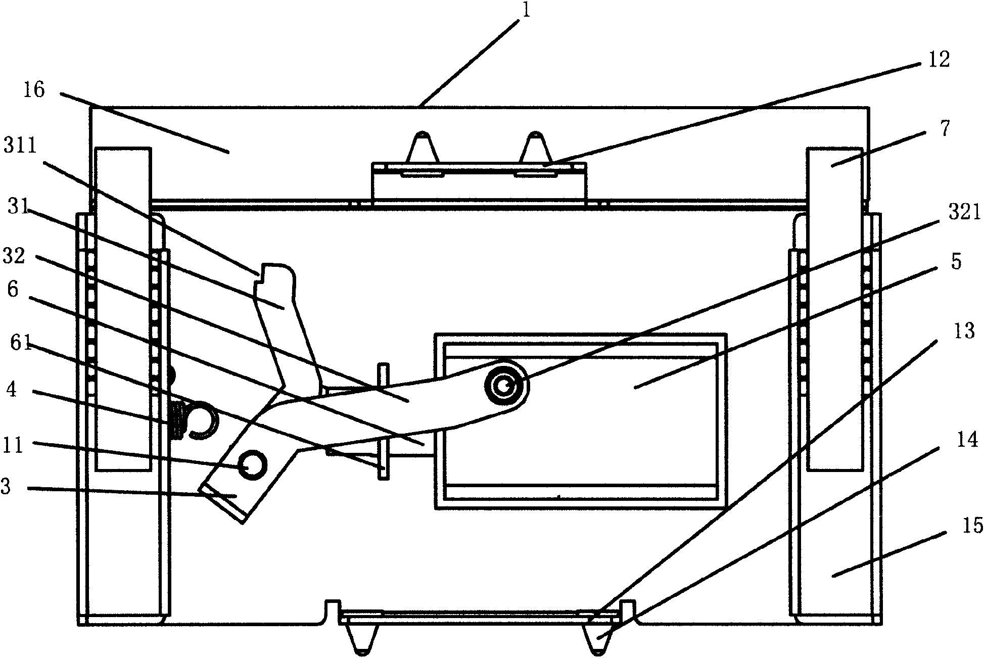
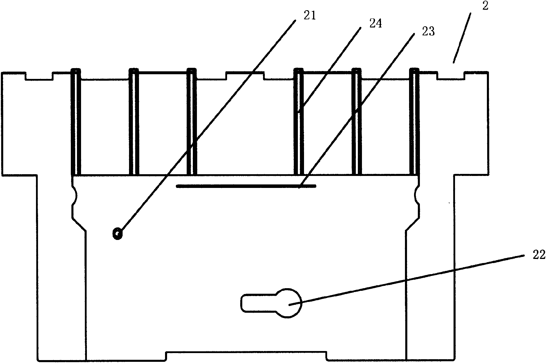
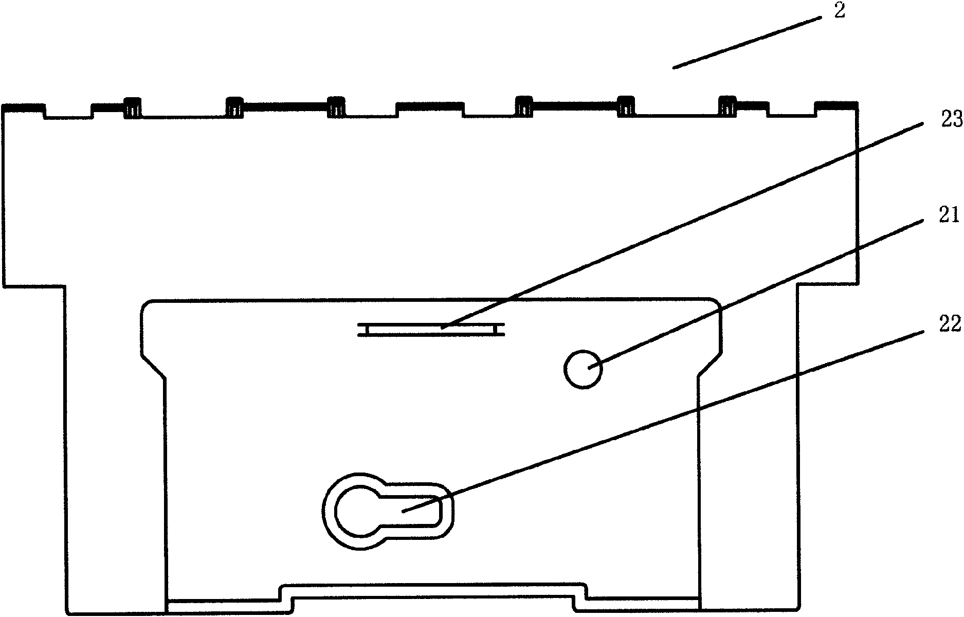
[0020] Such as Figures 1 to 5 As shown, the electromagnetic valve cash outlet of the present invention includes a bracket 1 and a cash outlet door 2, the bracket 1 is provided with a cash outlet 16, the cash outlet 2 can completely cover the cash outlet 16, and the cash outlet 2 passes through the sliding mechanism. Slidingly connected with the bracket 1 in the vertical direction, the bracket 1 is rotatably connected with a "V"-shaped toggle mechanism 3, the toggle mechanism 3 includes a rotating leg 31 and a toggle leg 32, and the toggle mechanism 3 is used to rotate the legs 31 and The connection point of the toggle leg 32 is the rotation of the rotating shaft, the pivot leg 31 is connected to the support on one side through the horizontal spring 4, and the electromagnet 5 is connected to the other side of the pivot leg 31 in the horizontal direction, and the free ...


PUM


Abstract

The invention discloses a paper money outlet door of an electromagnetic valve, utilizing an electromagnet as a driving tool. The paper money outlet door of the electromagnetic valve comprises a bracket, wherein, the bracket is provided with a paper money outlet position, the front side of the paper money outlet position is provided with a paper money outlet door plate which can completely cover a paper money outlet, the paper money outlet door plate is in slide connection with the vertical direction of the bracket by a slide mechanism, the bracket is connected with a V-shaped toggle mechanism in a rotation way, the toggle mechanism comprises a rotating support leg and a toggle support leg, the toggle mechanism rotates by taking the connection point of the rotation support leg and the toggle support leg as a rotating shaft, the rotating support leg is connected with the bracket at one side by a horizontal spring and is connected with an electromagnet towards the other side of a horizontal direction, the free end of the toggle support leg forwards forms a shaft pin, the corresponding position of the paper money outlet door plate is provided with a toggle hole which can sleeve the shaft pin, the paper money outlet door plate backwards forms a spacing piece capable of supporting against the rotating support leg, the outer side of the free end of the rotating support leg is provided with a gap, and the spacing piece can be completely clamped into the gap. The invention has simple structure, convenient operation, low production cost and convenient installation and maintenance and is not easy to generate errors.

Description

technical field [0001] The invention relates to a cash delivery door, in particular to a cash delivery door using an electromagnet as a driving tool. Background technique [0002] The structure of the current cash-out door is relatively complicated, and it is more troublesome to assemble, which leads to a relatively high cost of putting into production. In addition, the driving mode of the current cash-out door is driven by a motor, which not only affects the rotation position of the motor The control accuracy requirements of the machine are very high, and it is easy to break down. After the power is cut off, the self-locking cannot be restored, and after the motor is used for a certain period of time, there will be errors in its control, which will affect the normal operation of the banknote door. Contents of the invention [0003] Aiming at the above shortcomings, the present invention provides an electromagnet-driven cash delivery door with simple structure, convenient ...

Claims


Application Information

Patent Timeline
Patent Type & Authority Applications(China)
IPC IPC(8): G07D11/00
Inventor 何振东廖建华
Owner GUANGZHOU KINGTELLER TECHNOLOGY CO LTD
Learn More