
Electromagnetic touch device of transparent antenna board

A touch device and antenna board technology, applied in the direction of electrical digital data processing, input/output process of data processing, instruments, etc., can solve the problem of high power consumption, affecting product life, aging speed of electromagnetic induction antenna board and electromagnetic induction control board Speed ​​and other issues, to achieve the effect of reducing operating current and power consumption, reducing installation difficulty, and shortening the effective distance

Active Publication Date: 2010-01-06
HANVON CORP
View PDF0 Cites 10 Cited by
  • Summary
  • Abstract
  • Description
  • Claims
  • Application Information

AI Technical Summary

Problems solved by technology

However, this greatly increases the difficulty of installing the display device, resulting in a low product yield
On the other hand, since the electromagnetic induction antenna board needs to be placed behind the display module, there is a considerable distance from the electromagnetic pen. In order to ensure that the electromagnetic pen can be used normally on the display screen, the electromagnetic touch device must have a relatively large operating current. It consumes a lot, and it is easy to cause the electromagnetic induction antenna board and electromagnetic induction control board of the electromagnetic touch device to age quickly, which affects the product life.

Method used


Image

  • Electromagnetic touch device of transparent antenna board
  • Electromagnetic touch device of transparent antenna board
  • Electromagnetic touch device of transparent antenna board

Examples


Embodiment Construction

[0031] The technical solutions of the present invention will be further described below in conjunction with the accompanying drawings and embodiments.

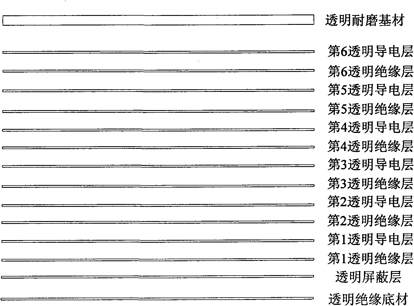
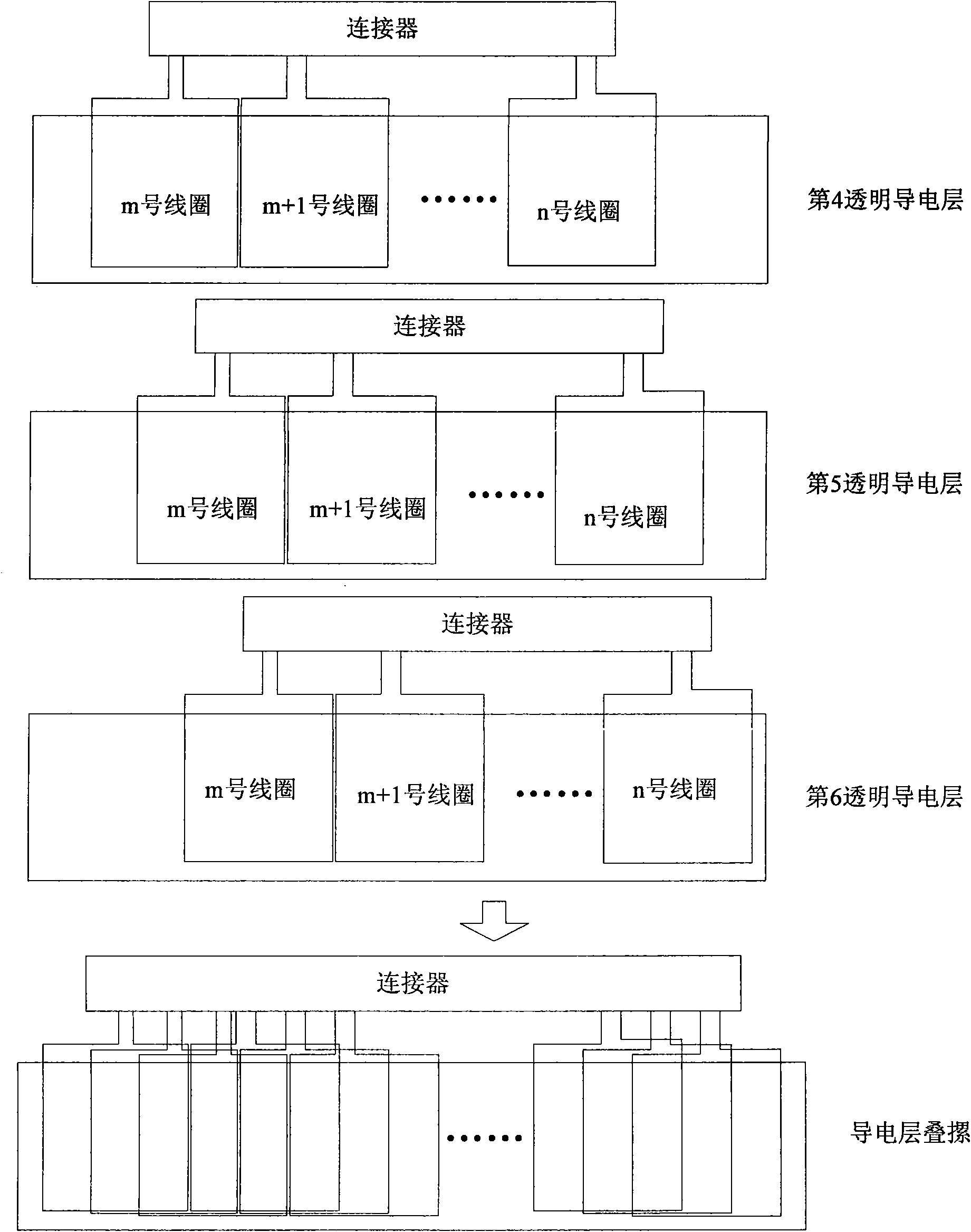
[0032] The electromagnetic touch device of the transparent antenna board of the present invention is composed of an electromagnetic induction control board, an electromagnetic induction antenna board and an electromagnetic pen. The electromagnetic induction control board emits electromagnetic waves through the electromagnetic induction antenna board. Within the range of generated electromagnetic waves, the electromagnetic pen receives electromagnetic waves to generate weak energy. Through this energy, the electromagnetic pen transmits electromagnetic signals to the electromagnetic induction antenna board, and the electromagnetic induction antenna board senses the electromagnetic waves. The electromagnetic signal emitted by the pen is transmitted to the electromagnetic induction control board, and the electromagnetic induction c...


PUM


Abstract

The invention discloses an electromagnetic touch device of a transparent antenna board and belongs to the field of computer external input equipment. The electromagnetic touch device of the transparent antenna board comprises an electromagnetic induction control panel, an electromagnetic induction antenna board and an electromagnetic pen, wherein the electromagnetic induction antenna board comprises at least six groups of transparent insulation layers and transparent conductive layers, a transparent wearable base material, a connector, a transparent shielding layer and a transparent insulation substrate. The wire outlet ends of the transparent conductive layers are connected with the electromagnetic induction control panel through the connector; the transparent wearable base material is arranged above the last transparent conductive layer; the transparent conductive layer is arranged below the first transparent insulation layer; and the transparent insulation substrate is arranged below the transparent shielding layer. In the electromagnetic touch device of the invention, the electromagnetic induction antenna board is arranged on the front face of a display module so as to reduce installation difficulties, shorten the distance between the electromagnetic induction antenna board and an electromagnetic pen, and lower the work current and power consumption of the electromagnetic touch device. The electromagnetic touch device of the invention can be applied to equipment such as handwriting computers, drafting boards, telephones, electronic books and the like.

Description

technical field [0001] The invention relates to the field of computer peripheral input equipment, in particular to an electromagnetic touch device. Background technique [0002] Electromagnetic touch technology is favored by the market due to its high positioning accuracy, the ability to obtain pen tilt angle and pressure information, and not affect the quality of screen display when used in the display field. It is widely used in handwriting computers, drawing screens, drawing tablets, handwriting, etc. Tablets, mobile phones, e-books and other devices. When the electromagnetic touch technology is used in the display field, users can write and draw directly on the display screen with a special electromagnetic pen just like writing and drawing on paper with a pen, realizing the function of "what you write is what you see". [0003] The electromagnetic touch device generally consists of an electromagnetic induction control board, an electromagnetic induction antenna board an...

Claims


Application Information

Patent Timeline
IPC IPC(8): G06F3/046G06F3/033G06F3/0354
Inventor 侯涛王杰尹航
Owner HANVON CORP
Learn More