Bellows of rotating mirror framing camera without theory error

A framing camera and rotating mirror technology, which is applied to cameras, camera bodies, instruments, etc., can solve the problems such as the inability to achieve constant velocity scanning of the exit pupil aperture array, the non-uniformity of photographing frequencies, and improve the accuracy of interpretation time. , The effect of reducing the time base interpretation error and ensuring the uniformity

Active Publication Date: 2010-01-06
SHENZHEN UNIV
View PDF0 Cites 4 Cited by
  • Summary
  • Abstract
  • Description
  • Claims
  • Application Information

AI Technical Summary

Problems solved by technology

[0008] The technical problem to be solved by the present invention is that the camera obscura of the rotating mirror framing camera in the prior art cannot realize constant-velocity scanning of the exit pupil diaphragm array, thus causing photography For the defect of frequency inhomogeneity, provide a camera obscura with no principle error for the rotating mirror framing camera, which can realize constant-speed scanning on the exit pupil array when the rotating mirror rotates at a constant speed, thus ensuring the uniformity of the photography frequency

Method used


Image

  • Bellows of rotating mirror framing camera without theory error
  • Bellows of rotating mirror framing camera without theory error
  • Bellows of rotating mirror framing camera without theory error

Examples


Embodiment Construction

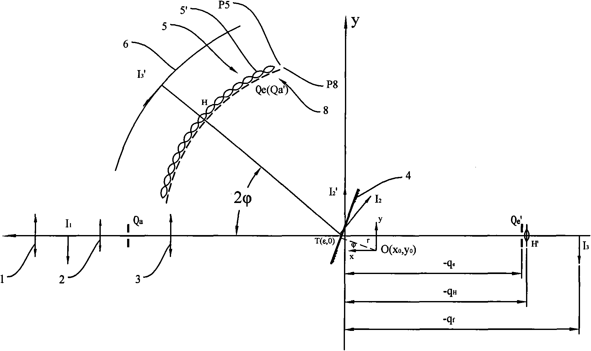
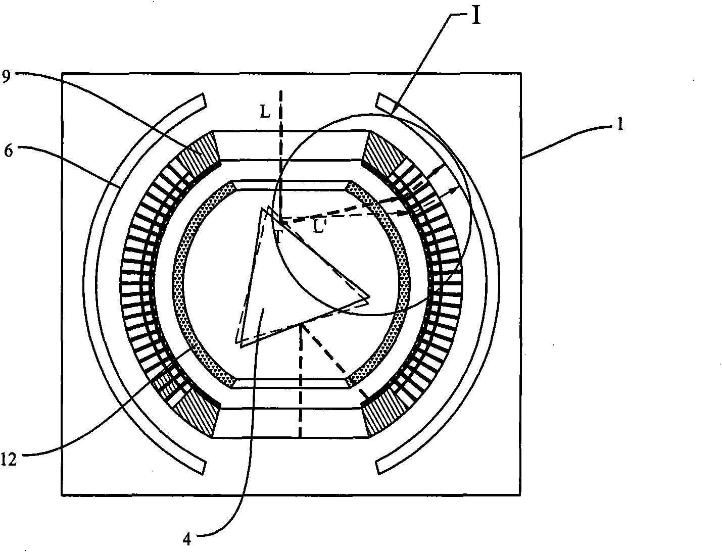
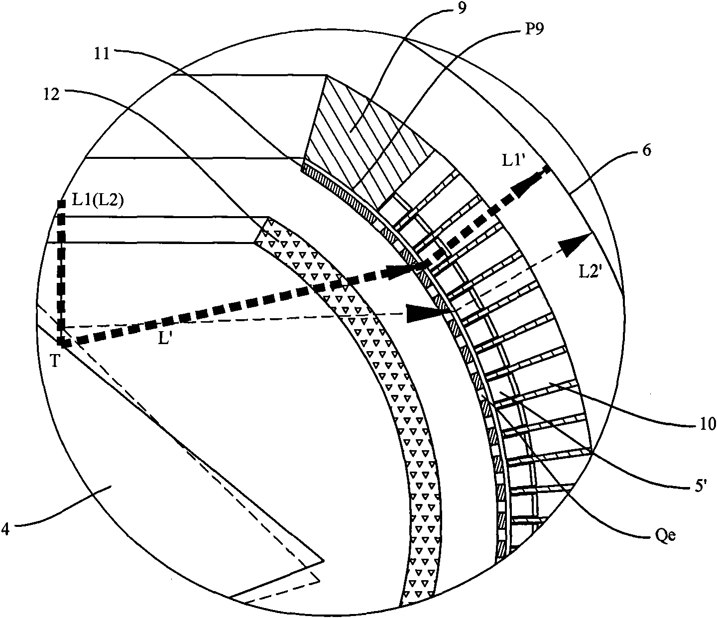
[0037] like figure 1 As shown, the camera obscura of the rotating mirror framing camera constructed based on Miller theory usually includes a casing 7 and a rotating mirror 4 arranged in the casing 7, a relay lens array 5 and a recording image plane 6, and the relay lens array 5 is composed of multiple An array of relay lenses 5 ′ is formed, each relay lens 5 ′ is provided with an exit pupil diaphragm Qe, and each exit pupil diaphragm Qe forms an exit pupil diaphragm array 8 . The image captured by the lens group outside the camera obscura enters the casing 7 through the aperture stop Qa provided at the entrance of the camera obscura, and the lens group can include an objective lens 1 for forming a primary image and a secondary image I for forming 2 The eyepiece 2 and the field lens 3, the aperture stop Qa is used to control the aperture of the imaging beam.

[0038] In the plane perpendicular to the rotation center of the rotating mirror, the secondary image I 2 The importe...


PUM


Abstract

The invention relates to a bellows of a rotating mirror framing camera, which comprises a bellows body and a rotating mirror, a relay lens array, an exit pupil diaphragm array and an image recording surface which are arranged in the bellows body. A secondary image I2 which is introduced from the outside of the bellows body is imaged on the rotating mirror and forms a final image on the image recording surface through the exit pupil diaphragms and the relay lenses after being mirrored by the rotating mirror; the image of an aperture diaphragm arranged on the bellows body is imaged on the exit pupil diaphragms through the rotating mirror; and the center of each exit pupil diaphragm is arranged on a cylindrical surface using a first Pascal helical line as an alignment line. By arranging the center of each exit pupil diaphragm on the cylindrical surface using the first Pascal helical line as the alignment line, constant scanning of the exit pupil diaphragm array is realized and the uniformity of the photographing frequency is ensured. The invention further discloses a technical scheme of respectively arranging the principal point of each relay lens in the relay lens array and the image recording surface on the cylindrical surfaces using a second Pascal helical line and a third Pascal helical line as alignment lines, thereby eliminating the theory error in the prior art and increasing the resolution of the camera.

Description

【Technical field】 [0001] The invention relates to ultra-high-speed photography technology, more specifically, to a camera obscura with no principle error for rotating mirror and framing camera. 【Background technique】 [0002] High-speed photography equipment is an extension of the time resolution ability of the human eye, which can record the temporal and spatial information in the transient process, thus providing a powerful tool for the analysis and research of the transient process. Microsecond and submicrosecond time resolution high-speed photographic equipment. Among all kinds of high-speed photographic instruments that meet this requirement, the rotating mirror framing camera has the characteristics of large frame size, multiple frames, high spatial resolution, and wide photographic frequency range. It can undertake 10 4 ~10 7 fps (frames per second) research tasks for most ultrafast processes in the ultrahigh-speed photography band. Therefore, after the research f...

Claims


Application Information

Patent Timeline
Patent Type & Authority Applications(China)
IPC IPC(8): G03B39/00
CPCG03B17/04
Inventor 李景镇龚向东吴庆阳
Owner SHENZHEN UNIV
Why Eureka
Try Eureka