
Air bag arrangement

An inflatable device and airbag technology, applied in transportation and packaging, pedestrian/passenger safety arrangements, vehicle components, etc.

Active Publication Date: 2010-01-06
VOLVO CAR CORP
View PDF3 Cites 3 Cited by
  • Summary
  • Abstract
  • Description
  • Claims
  • Application Information

AI Technical Summary

Problems solved by technology

[0006] However, there is still room for further improvement for the above-mentioned devices and systems

Method used


Image

  • Air bag arrangement
  • Air bag arrangement
  • Air bag arrangement

Examples


Embodiment Construction

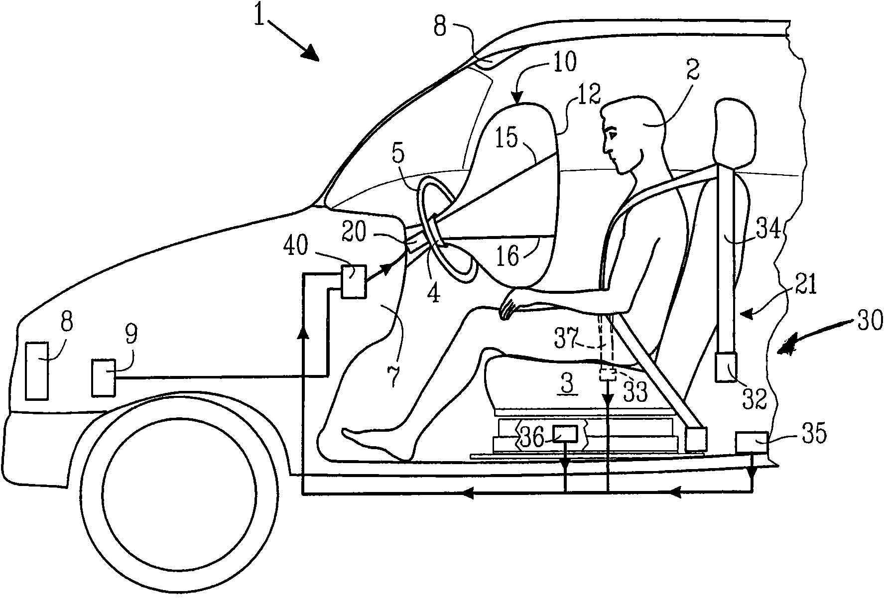
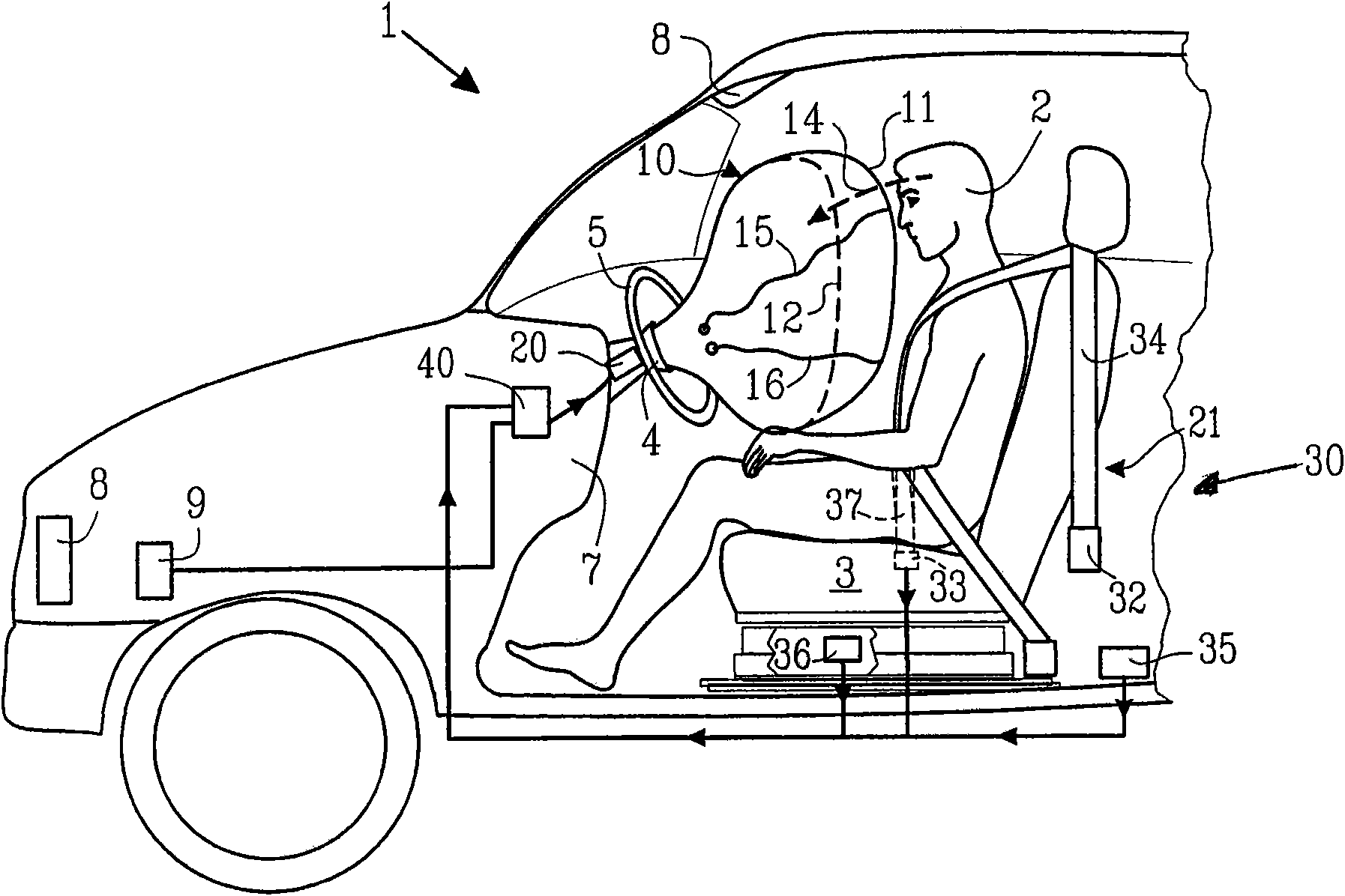
[0023] Figures 1A-1B A passenger 2 (in this example the driver of the vehicle 1 ) is shown in the driver's seat 3 . The airbag 10 deploys from an airbag housing (in this embodiment of the invention, the hub 4 of the steering wheel 5 located on the dashboard 7 of the vehicle 1 ). The airbag deployment sensors 8 and 9 are arranged to cooperate with the airbag 10 . In the illustrated embodiment of the invention, the processing unit 40 is arranged to drive the deployment of the airbag 10 such that the airbag deployment sensors 8 , 9 are connected to the processing unit 40 , which in turn is connected to the airbag inflator 20 . As shown in the figure, only one airbag 10 is deployed, but within the protection scope of the present invention, a plurality of airbags can be deployed simultaneously or sequentially, for example, 2, 3, 4, 5 or more airbags can be deployed .

[0024] The airbag 10 comprises a first deployment volume 11 and a second deployment volume 12 . shown in Fi...


PUM


Abstract

The present invention relates to an air bag deployment arrangement and a method for deploying an air bag using the air bag deployment arrangement. The air bag can be deployed into at least a first and a second deployment volume which is deployed dependent on the occupant position into at least a first or a second inflation pressure. The arrangement comprises at least one occupant positioning sensor arrangement (30), an inflator device (20) to inflate said at least one air bag (10), and at least one impact sensor (8, 9). The arrangement provides for a safe air bag arrangement which can be deployed into a multiple of ways and which therefore is very flexible and versatile.

Description

technical field [0001] The invention relates to an airbag deployment device comprising at least a first and a second deployment volume which is deployed depending on the position of a passenger. Background technique [0002] Air bag devices have been widely used in the automotive industry over the past few decades and have provided enhanced safety features for passengers. In motor vehicles, air bags are typically located in the steering wheel hub, in the recess of the instrument panel, in the seats, and in the door panels or A, B and C pillars. Other positions are of course also possible. Regardless of the position of the airbag, the airbag needs to inflate rapidly at the right time. [0003] The airbag is typically in fluid communication with a gas emitting inflator, which in turn is typically connected to a crash sensor. During, for example, a frontal collision between two cars, sensors (eg, accelerometers) detect the rapid deceleration of the vehicles during impact. T...

Claims


Application Information

Patent Timeline
Patent Type & Authority Applications(China)
IPC IPC(8): B60R21/233B60R21/276B60R21/013B60R21/015
CPCB60R2021/01211B60R21/2342B60R21/01546B60R2021/01554B60R21/015B60R2021/23384
Inventor 彼得·哈达弗雷德里克·海乌林
Owner VOLVO CAR CORP
Learn More