
Bidirectional coupling device with same or different transmission characteristics

A technology of coupling device and transmission characteristics, applied in the field of coupling device, can solve problems such as single performance limitation

Inactive Publication Date: 2010-01-06
杨泰和
View PDF4 Cites 9 Cited by
  • Summary
  • Abstract
  • Description
  • Claims
  • Application Information

AI Technical Summary

Problems solved by technology

[0005] The other is a rigid coupler, which is a variety of existing rigid coupling devices such as mechanical clutches, electromagnetic clutches, pneumatic, hydraulic, mechanical or centrifugal force-driven friction clutches. When the rotary kinetic energy between the sides is normally transmitted, the two are synchronous and rigidly coupled without slip. The single performance of the above two couplers often causes limitations in application.

Method used


Image

  • Bidirectional coupling device with same or different transmission characteristics
  • Bidirectional coupling device with same or different transmission characteristics
  • Bidirectional coupling device with same or different transmission characteristics

Examples


Embodiment Construction

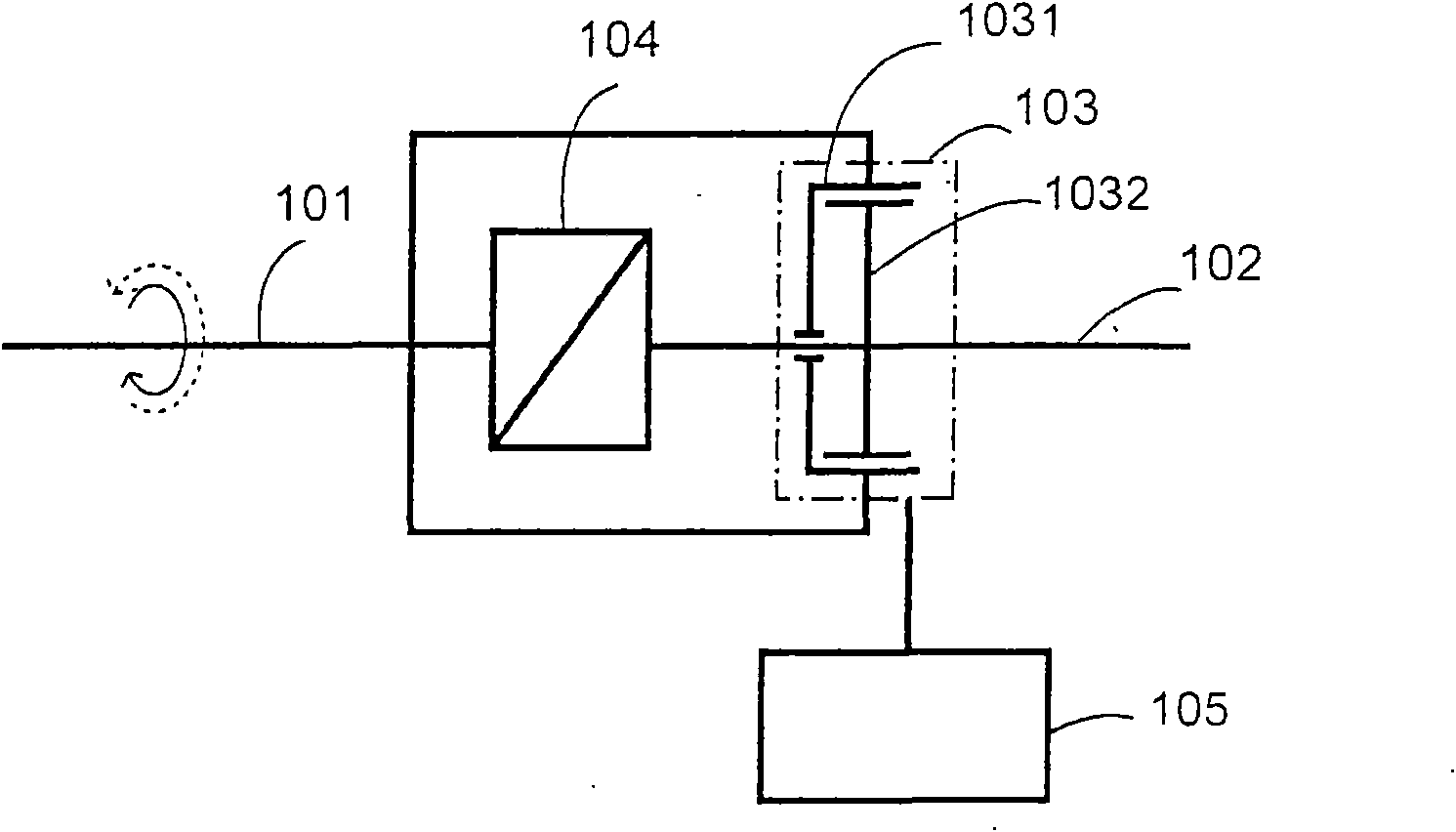
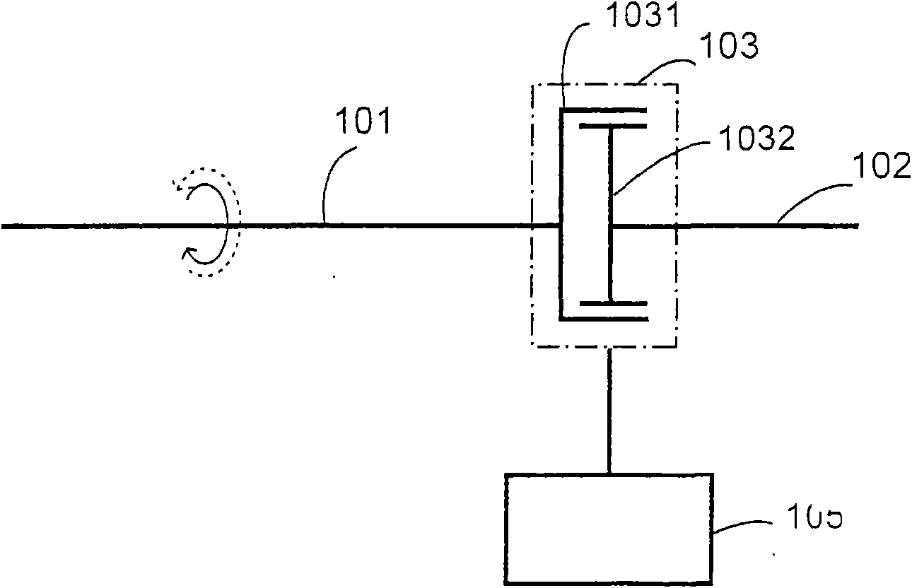
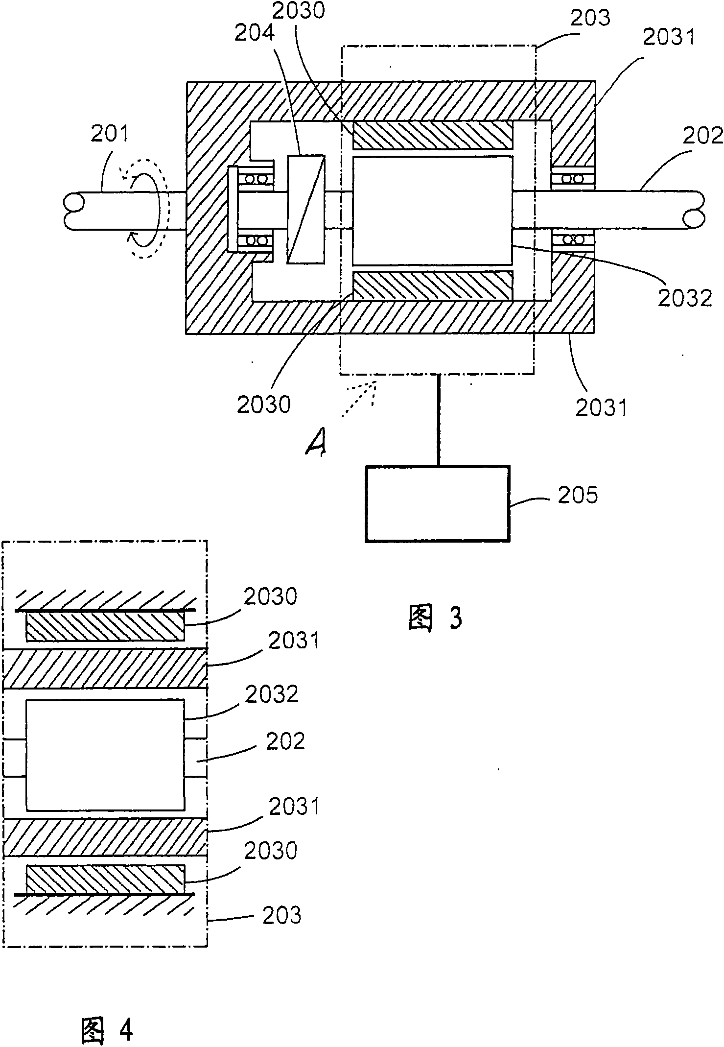
[0086] The embodiment of the two-way coupling device with the same or different transmission characteristics of the present invention can be made into the following structural combinations within the aforementioned specific defined functional scope, and its main constituent features include:

[0087] There are flexible coupling devices with specific or adjustable flexibility values ​​or torques. The flexible coupling devices include conventional mechanical sliding friction couplings, viscous fluid sliding friction couplings, eddy current couplings, magnetic fluid or A magnetic powder coupler, a fluid coupler driven by gas or liquid, or a double-acting power generation effect coupler is composed of mechanical, electromagnetic or other physical structures; the flexible coupling device has at least one first input and output end and at least one The second input-output terminal, which transmits the rotary kinetic energy from the first input-output terminal to the transmission dire...


PUM


Abstract

The invention relates to a bidirectional coupling device with same or different transmission characteristics and provides a transmission device part with same or different transmission characteristics and wide application range, in particular to a special bidirectional rotary transmission coupler with bidirectional transmission rotary kinetic energy of at least one first output / input end and at least one second output / input end. A transmission characteristic which can be used as a continuous rotary rotation difference and presents a special or adjustable flexibility value or toque can exist between the first output / input end and the second output / input end driven by the first output / input end, and another transmission characteristic which can be used as a continuous rotary rotation difference and presents a special or adjustable flexibility value or toque or a rigid transmission characteristic without the rotation difference can be selected as required to exist between the second output / input end and the first output / input end driven by the second output / input end. The coupling device is arranged at the output end of a rotary power source, an input side of an unstable impact load, between the rotary power source and a ballistic flywheel or a damping flywheel, between the ballistic flywheel or the damping flywheel and the load or used for transmitting the rotary kinetic energy of other machinery.

Description

[0001] The present invention is a divisional application of application number: 200410074573.5, application date: September 7, 2004, and invention name: "Coupling device with the same or different transmission characteristics in both directions". technical field [0002] The invention belongs to transmission device components, in particular to a bidirectional coupling device with the same or different transmission characteristics. Background technique [0003] Existing couplers are usually divided into two types, one is a flexible coupling device that can be used for continuous rotary slip, such as a conventional mechanical sliding friction coupler, a viscous fluid sliding friction coupler, an eddy current coupler, etc. , magnetic fluid or magnetic powder coupler, gas or liquid-driven fluid coupler, double-action power generation effect coupler and other double-acting flexible coupling devices. [0004] When the rotary kinetic energy is transmitted between the input side and...

Claims


Application Information

Patent Timeline
Patent Type & Authority Applications(China)
IPC IPC(8): B60K17/02B60K17/26F16D13/00F16D35/00F16H41/00H02K49/00
Inventor 杨泰和
Owner 杨泰和
Learn More