Rapidly rotating vacuum pump

A vacuum pump, fast technology, applied in the direction of pumps, parts of pumping devices for elastic fluids, pump components, etc., can solve problems such as large costs

Active Publication Date: 2009-12-30
LEYBOLD HERAEUS GMBH & CO KG
View PDF0 Cites 2 Cited by
  • Summary
  • Abstract
  • Description
  • Claims
  • Application Information

AI Technical Summary

Problems solved by technology

Although in this way a safe active overspeed protection for rapidly rotating vacuum pumps can be realized with high technical effort and redundant hardware and software, considerable costs are incurred for this due to the high technical effort

Method used


Image

  • Rapidly rotating vacuum pump

Examples


Embodiment Construction

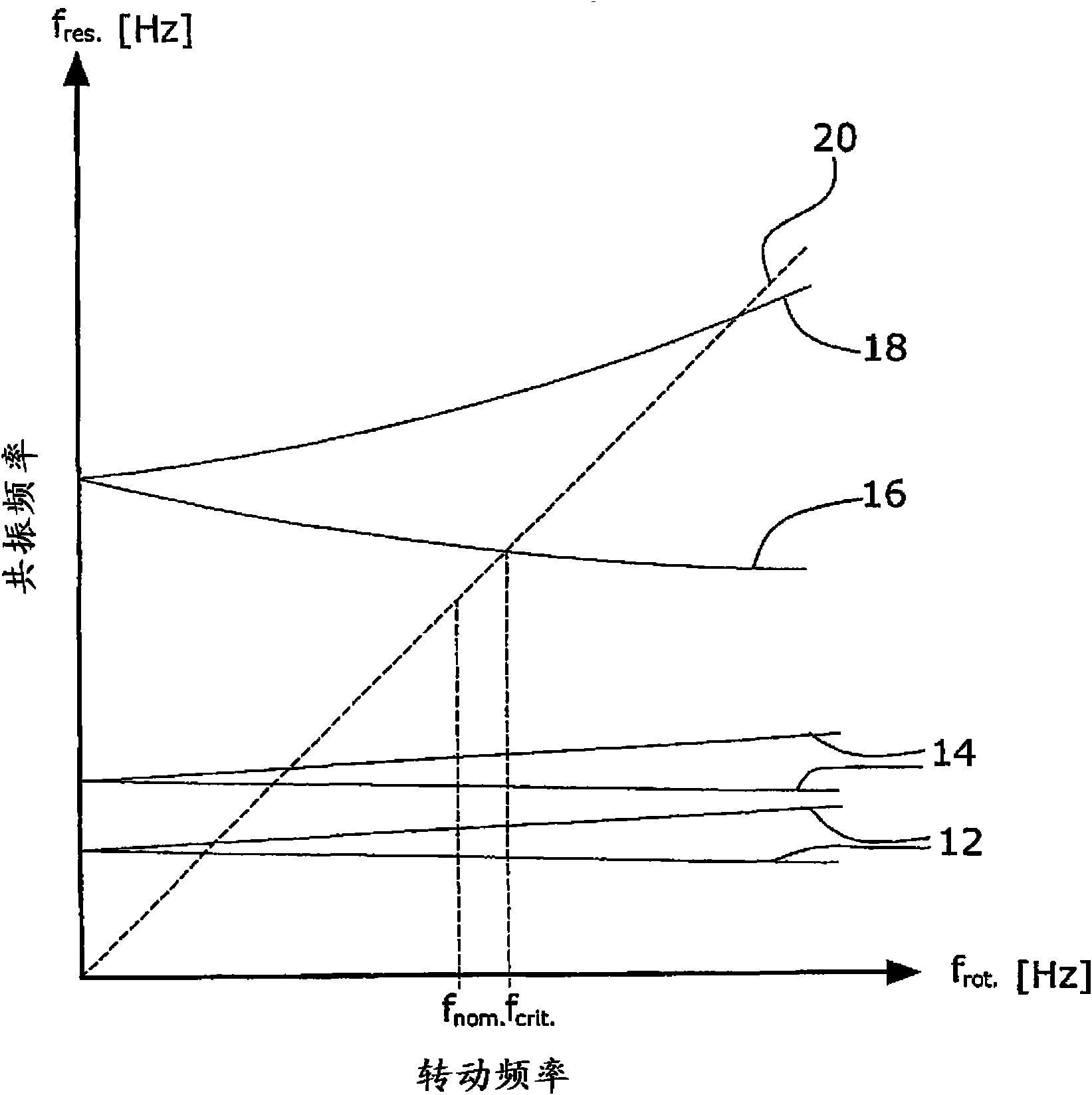
[0013] In the Campbell graph of the attached drawing, the rotation frequency f of the rotor is shown rot The resonance frequency of the rotor f res .

[0014] The rapidly rotating vacuum pump here is a turbomolecular vacuum pump, and the rotor of the turbomolecular vacuum pump is completely five-axis supported by magnetic bearings. The rotor is driven by an electric drive motor and has a constant fixed rated rotation frequency f nom Running.

[0015] In the graph, firstly, the critical resonance frequency curves 12 and 14 of the rigid body are shown two by one in the low speed range. These resonance frequencies vary with the rotation frequency f of the rotor rot Change to a relatively small degree. In addition, in the range of higher rotation speeds, the bending-critical reverse rotation resonance frequency curve 16 and the bending-critical co-rotation resonance frequency curve 18 are shown. In addition, a so-called position vector 20 is shown by a broken line. Where the position ...


PUM


Abstract

The invention relates to a rapidly rotating vacuum pump comprising a magnet-mounted rotor driven by an electric drive motor and having a fixed constant nominal rotational frequency (fnom). The rotor and the rotor bearing are desinged to enable a reverse rotating resonance frequency (fcrit) of bend critical to be positioned between more than 3% and max 30% of nominal rotational frequency (fnom)for preventing overspeed.

Description

Technical field [0001] A fast-rotating vacuum pump, especially a magnetically supported non-positive displacement turbomolecular pump, requires reliable overspeed protection, because the centrifugal force overspeed not only causes damage to the vacuum pump, but also poses a high degree of danger to people. Background technique [0002] In practice, complex electronic components are used for overspeed protection of rapidly rotating vacuum pumps. The electronic components monitor the rotation speed of the rotor or the electric drive motor and limit the rotation speed electronically. Although in this way it is possible to achieve safe and active overspeed protection for the rapidly rotating vacuum pump by means of high technical expenditure and redundant hardware and software, considerable costs are incurred for this purpose due to the high technical expenditure. Summary of the invention [0003] The object of the present invention is to provide a fast-rotating vacuum pump with sim...

Claims


Application Information

Patent Timeline
Patent Type & Authority Applications(China)
IPC IPC(8): F04D19/04F04D29/06F04D29/058
CPCF04D29/668F04D29/058F04D19/042F04D19/04F04D29/06F04D29/58
Inventor 海因里希·恩伦德尔克里斯蒂安·哈里希
Owner LEYBOLD HERAEUS GMBH & CO KG
Why Eureka
Try Eureka