A piezoresistive pressure-measuring plug for a combustion engine

A piezoresistive, internal combustion engine technology, applied in the direction of internal combustion engine testing, measuring devices, measuring rapid changes, etc., can solve problems such as sensor signal deviation, and achieve the effect of low cost

Active Publication Date: 2011-09-14
SESATA SCI & TECH CHANGZHOU CO LTD
View PDF4 Cites 0 Cited by
  • Summary
  • Abstract
  • Description
  • Claims
  • Application Information

AI Technical Summary

Problems solved by technology

In known pressure-measuring plugs provided with a plug rod, mounting forces on the housing lead to deviations in the sensor signal, so that the electronics must compensate for this after the pressure-measuring plug has been installed in the internal combustion engine

Method used


Image

  • A piezoresistive pressure-measuring plug for a combustion engine
  • A piezoresistive pressure-measuring plug for a combustion engine
  • A piezoresistive pressure-measuring plug for a combustion engine

Examples


Embodiment Construction

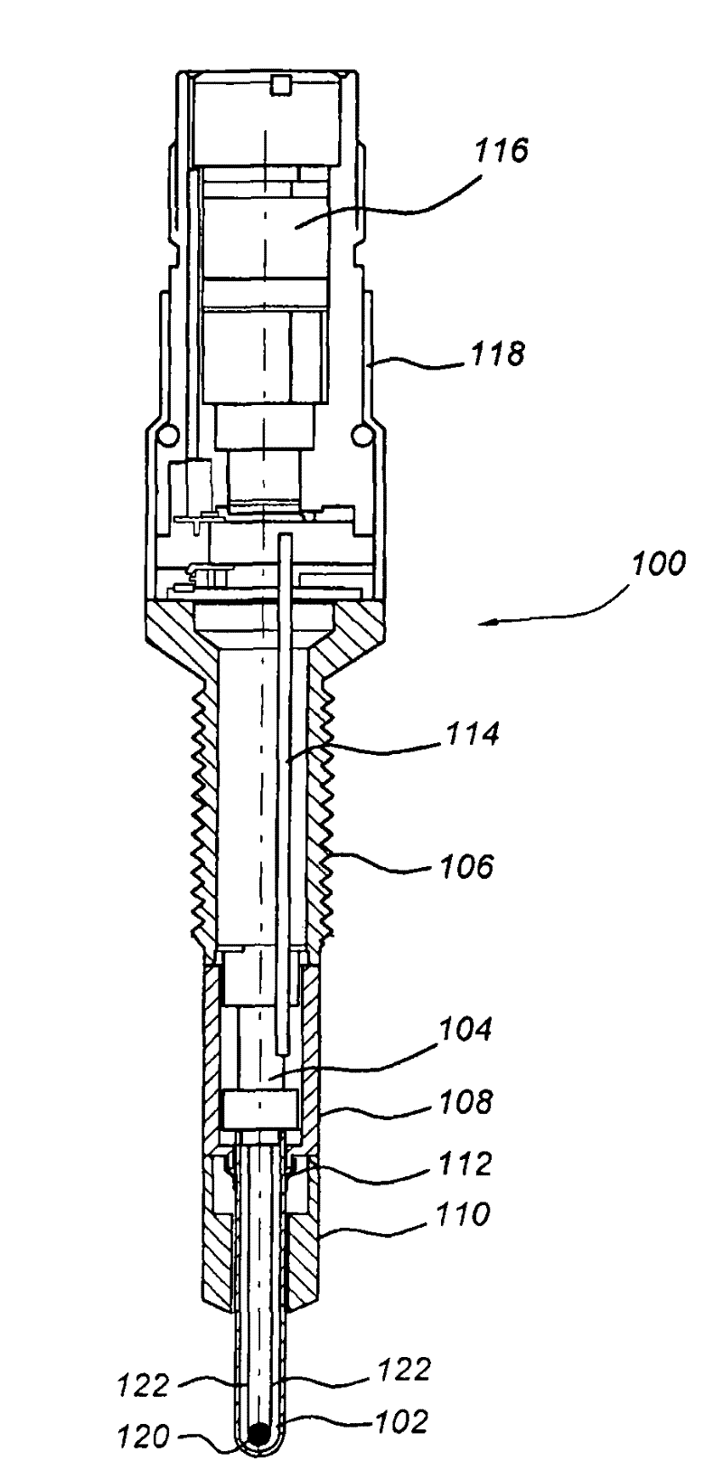
[0035] exist figure 1 A first embodiment of a pressure-measuring plug 100 according to the invention is shown in . The pressure measurement plug 100 comprises a plug stem 102 , a plug body 110 , 108 , 106 , a sensing structure 104 , a PWB 114 provided with sensor electronics and a sensor electrical connection 116 . The sensor electrical connection 116 is arranged in a housing 118 arranged to seal the cavity in the plug body 106, 108, 110 in which the sensing structure 104 and sensor electronics 114 are located from the external environment.

[0036] exist figure 1In the example of embodiment shown in , the plug bodies 110, 108, 106 include a plug body lower portion 110, a plug body middle portion 108, and a plug body upper portion 106, which are mechanically connected together. The lower part 110 of the plug body is arranged on the combustion chamber side and has a sealing cone, by means of which the pressure measuring plug is sealed off from the combustion pressure at the c...


PUM

PropertyMeasurementUnit
resonance frequencyaaaaaaaaaa

Abstract

A piezoresistive pressure-measuring plug for a combustion engine for measuring a pressure is disclosed. The piezoresistive pressure-measuring plug comprises: a plug body for insertion into a cylinder of the combustion engine, a rod that is arranged in the plug body, a sensing structure comprising a piezoresistive element, that is arranged between the rod and the plug body in such a way that the sensing structure is acted upon, in use, by the pressure prevailing in the combustion chamber of the cylinder, whereby the rod transmits the pressure in the combustion chamber of the cylinder to the sensing structure due to the pressure in the combustion chamber leading to an axial motion of the rod relative to the plug body so as to apply a force to the sensing structure and a PWB; provided with sensor electronics for measuring and conditioning a resistance change. The sensing structure is arranged in the plug body and, in use is compressed in axial direction by the force applied to the sensing structure and a piezoresistive element mounted on the sensing structure to provide a resistance change when the sensing structure is compressed in axial direction. Furthermore, the PWB is arranged in the plug body. In this way a pressure-measuring plug is obtained with improved bandwidth and reduced build-in height.

Description

technical field [0001] The invention relates to a pressure measuring plug for an internal combustion engine having a plug body for insertion into a cylinder of the internal combustion engine, a plug rod arranged in the plug body and a sensing structure arranged in the following manner Between the plug rod and the plug body, that is: the sensing structure is subjected to the pressure in the combustion chamber of the cylinder, wherein the plug rod transmits the pressure in the combustion chamber of the cylinder to the sensing structure, and wherein the plug rod is arranged in The plug body is movable in an axial direction in a sliding manner relative to the plug body, so that the pressure in the combustion chamber causes the heating rod to move axially relative to the plug body, and due to this movement, the sensing structure is subjected to a force. Background technique [0002] Pressure measuring plugs of the above-mentioned type are known from US7228730 and US2005 / 0061063. ...

Claims


Application Information

Patent Timeline
Patent Type & Authority Patents(China)
IPC IPC(8): G01L23/18G01M15/04
CPCG01L23/18F23Q2007/002F23Q7/001Y10T29/42
Inventor M·G·J·博格斯C·R·兹沃洛P·T·J·杰尼森T·迪克H·G·托内曼A·F·兹维耶泽S·格朗海耶曾
Owner SESATA SCI & TECH CHANGZHOU CO LTD
Why Eureka
Try Eureka