Thermal head

A technology of thermal head and heating part, applied in the field of thermal head, can solve the problems of ribbon wrinkling, difficulty in grinding, ribbon breakage, etc., and achieve the effect of uniform heating distribution, good gloss and image degree

Inactive Publication Date: 2009-12-30
ALPS ALPINE CO LTD
View PDF4 Cites 0 Cited by
  • Summary
  • Abstract
  • Description
  • Claims
  • Application Information

AI Technical Summary

Problems solved by technology

In this case, it is very difficult to polish the folded electrodes arranged on the portion of the convex thermal storage layer at the largest inclination angle (the position away from the convex top) without losing its curvature.
Therefore, although the shorter the size of the foldback electrode, the easier the grinding operation becomes, but if it is too short, the heat distribution of the heating resistor required for printing cannot be formed.
Therefore, if the foldback electrode accumulates too much heat, the ribbon will be damaged (heat damaged) when the ribbon is removed, and adverse effects such as ribbon breakage or ribbon wrinkling may occur.

Method used


Image

  • Thermal head
  • Thermal head
  • Thermal head

Examples


Embodiment Construction

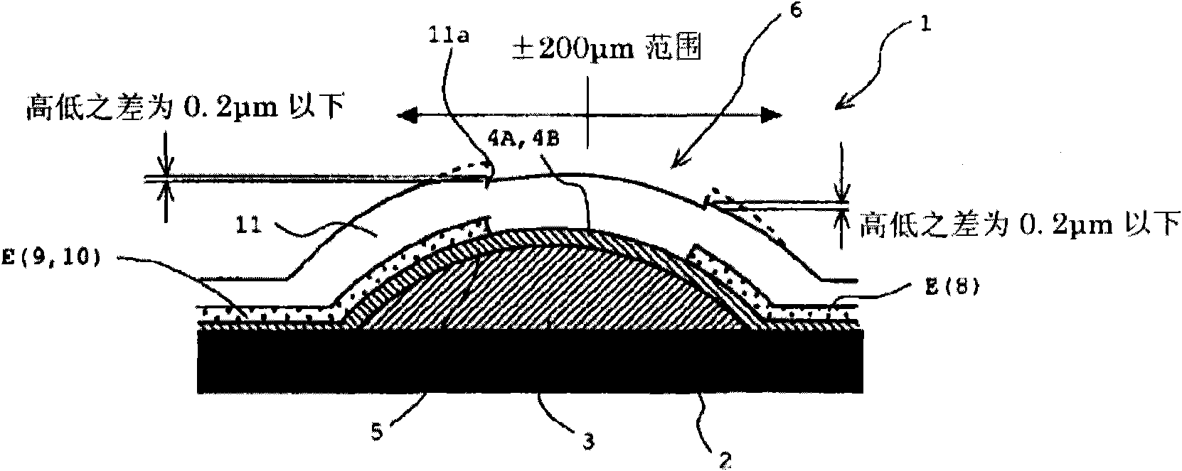
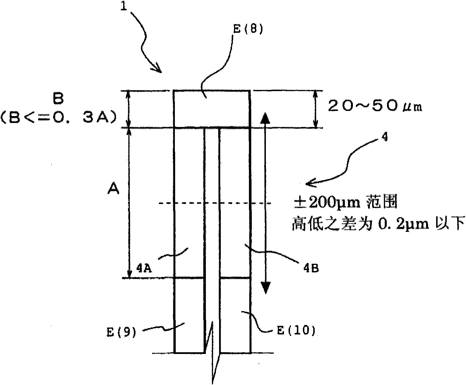
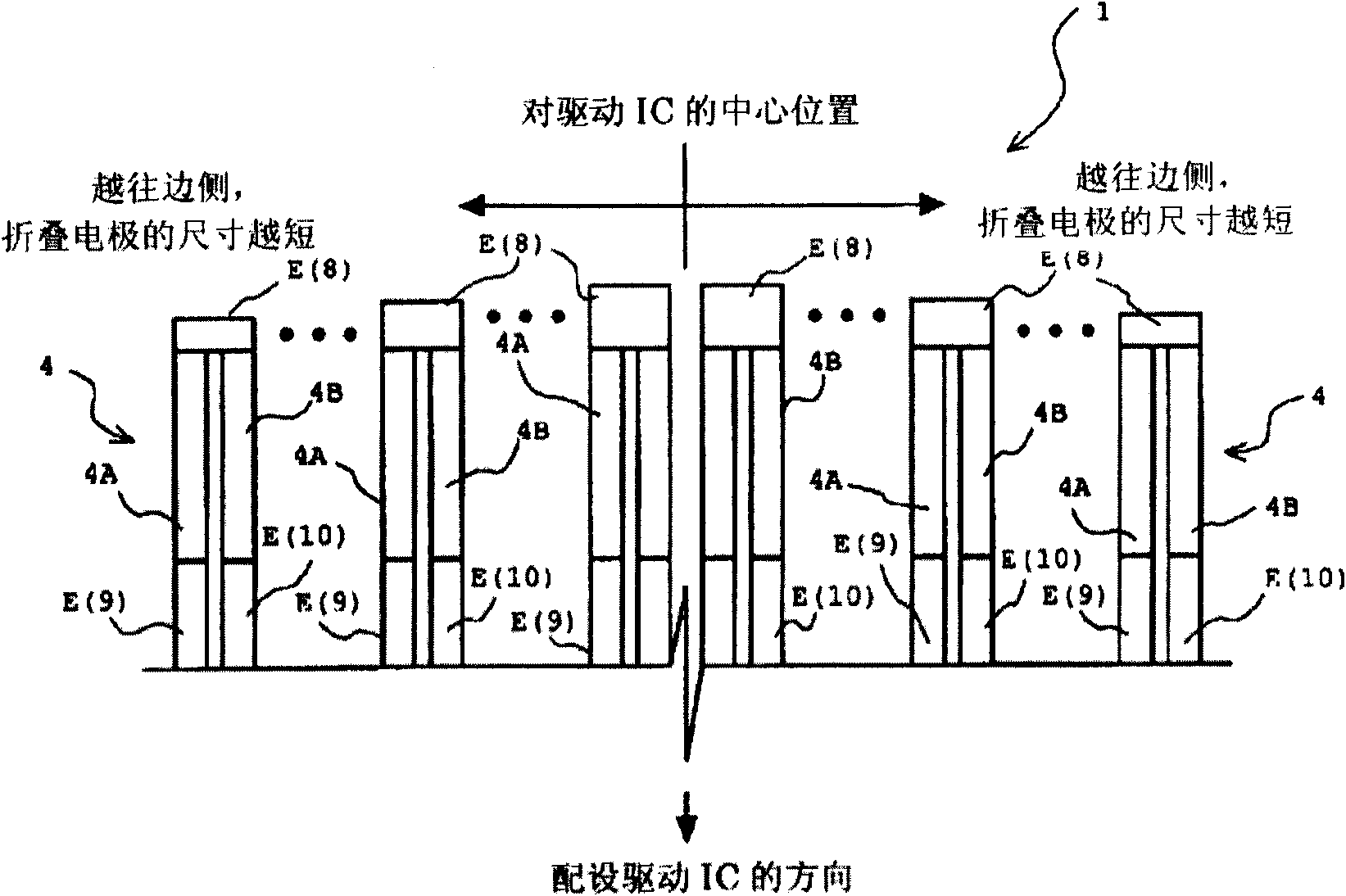
[0036] Such as figure 1As shown, the thermal head 1 of this embodiment includes a heat dissipation substrate 2 . A plurality of driver ICs (not shown) arranged in line in the main scanning direction perpendicular to the recording direction are arranged on the above-mentioned substrate 2 . Moreover, a heating element 6 is formed on the above-mentioned substrate 2, and the heating element 6 has: a heat storage layer 3 formed in a cylindrical shape with a heat insulating material such as glass; A pair of effective heating parts 4A, 4B of the heating resistor 4; an insulating layer (not shown in the figure), covers the surface of each heating resistor layer 5 and defines the plane size of the heating resistor 4, that is, the main plane perpendicular to the recording direction. The dimension in the scanning direction (width dimension) and the dimension in the sub-scanning direction (length dimension) serving as the recording direction; and the electrode layer E are composed of Al ...


PUM


Abstract

Provided is a thermal head in which the number of manufacturing processes or the cost does not increase and a heat distribution becomes uniform at the time of supplying electricity, so that a good printing result can be obtained, and in particular a good degree of gloss and image clarity in the printing result can be realized. The thermal head (1) includes a substrate (2); a plurality of driver ICs configured to be arranged in a main scanning direction on the substrate (2); a heater element (6) configured to include a heat storage layer formed on the substrate (2), a heating resistor layer which is made of a plurality of pairs of effective heating portions (4A and 4B) formed on the heat storage layer as a heating resistor, and an electrode layer which is patterned to supply electricity to the heating resistor layer; and a protective layer configured to cover a surface of the heater element (.6), wherein the electrode layer is provided with a folded electrode (8), a separate electrode (9) and a common electrode (10), and wherein the folded electrode (8) is formed by adjusting an area thereof such that a heat distribution of each heating resistor becomes uniform.

Description

technical field [0001] The present invention relates to a thermal head whose structure is most suitable for a small and thin thermal printer. Background technique [0002] A thermal head mounted on a printing section of a thermal printer includes a substrate, a plurality of driver ICs, a heat generating element, and a protective layer. The plurality of driver ICs are arranged on the substrate in the main scanning direction (longitudinal direction), and the protective layer Cover the heating element above. [0003] The above-mentioned heating element has: a heat storage layer formed of glazed glass or the like extending in the main scanning direction on the above-mentioned substrate; The main scanning direction dimension (width dimension) and the sub-scanning direction dimension (longitudinal direction) of the pair of effective heating portions have been specified, and the connecting portion connects one end of the pair of effective heating portions in the longitudinal direc...

Claims


Application Information

Patent Timeline
Patent Type & Authority Applications(China)
IPC IPC(8): B41J2/335B41J2/345
CPCB41J2/33545B41J2/3351B41J2/3357B41J2/33515
Inventor 佐佐木恒之寺尾博年安田由季子和宇庆知子
Owner ALPS ALPINE CO LTD
Why Eureka
Try Eureka