Restrain device and control method for excitation inrush current of transformer
一种突入电流、抑制装置的技术,应用在电路装置、高压/大电流开关、紧急保护电路装置等方向,能够解决无法正确地计算残留磁通等问题,达到抑制励磁突入电流的效果
- Summary
- Abstract
- Description
- Claims
- Application Information
AI Technical Summary
Problems solved by technology
Method used
Image

Examples
no. 1 approach
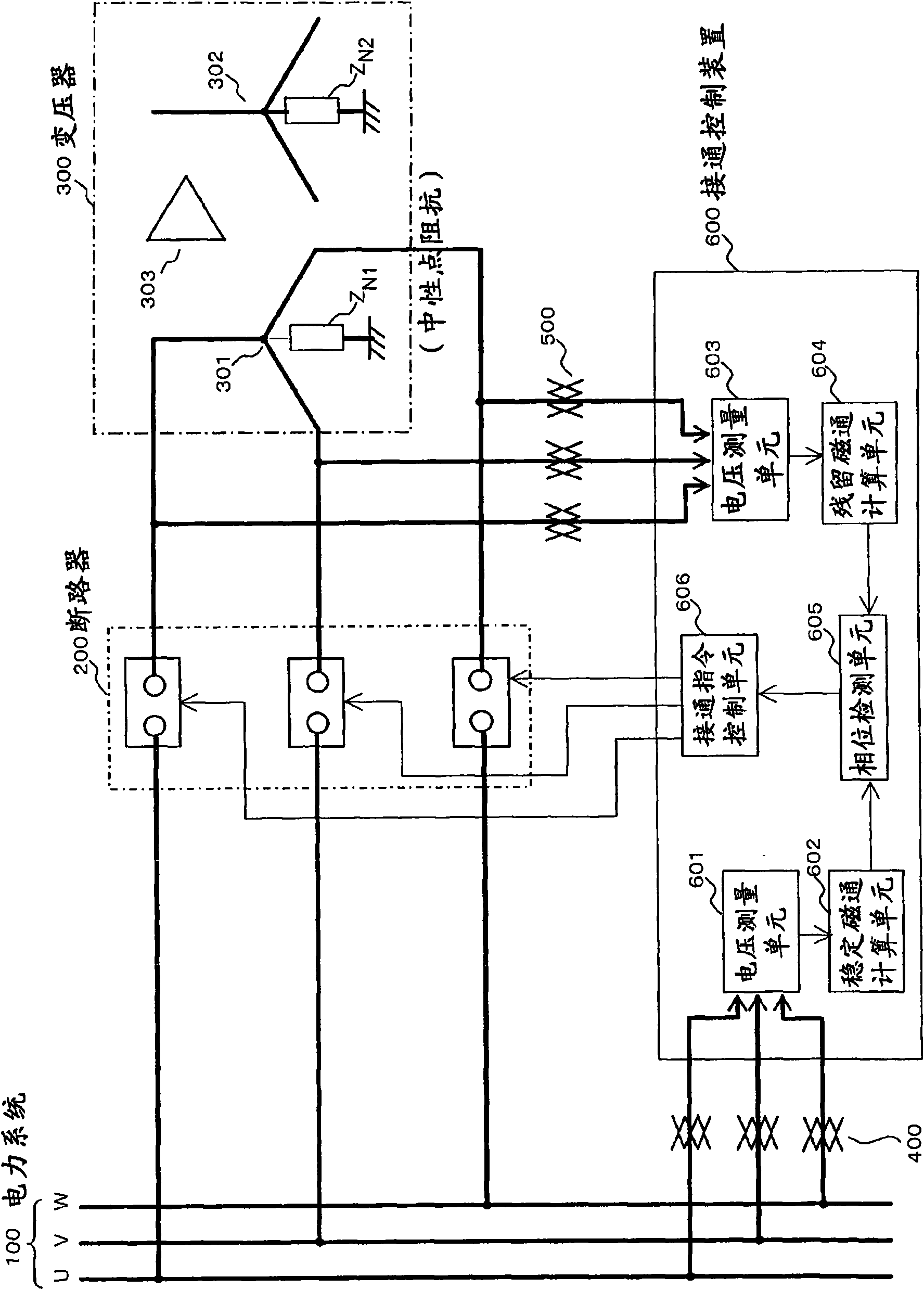
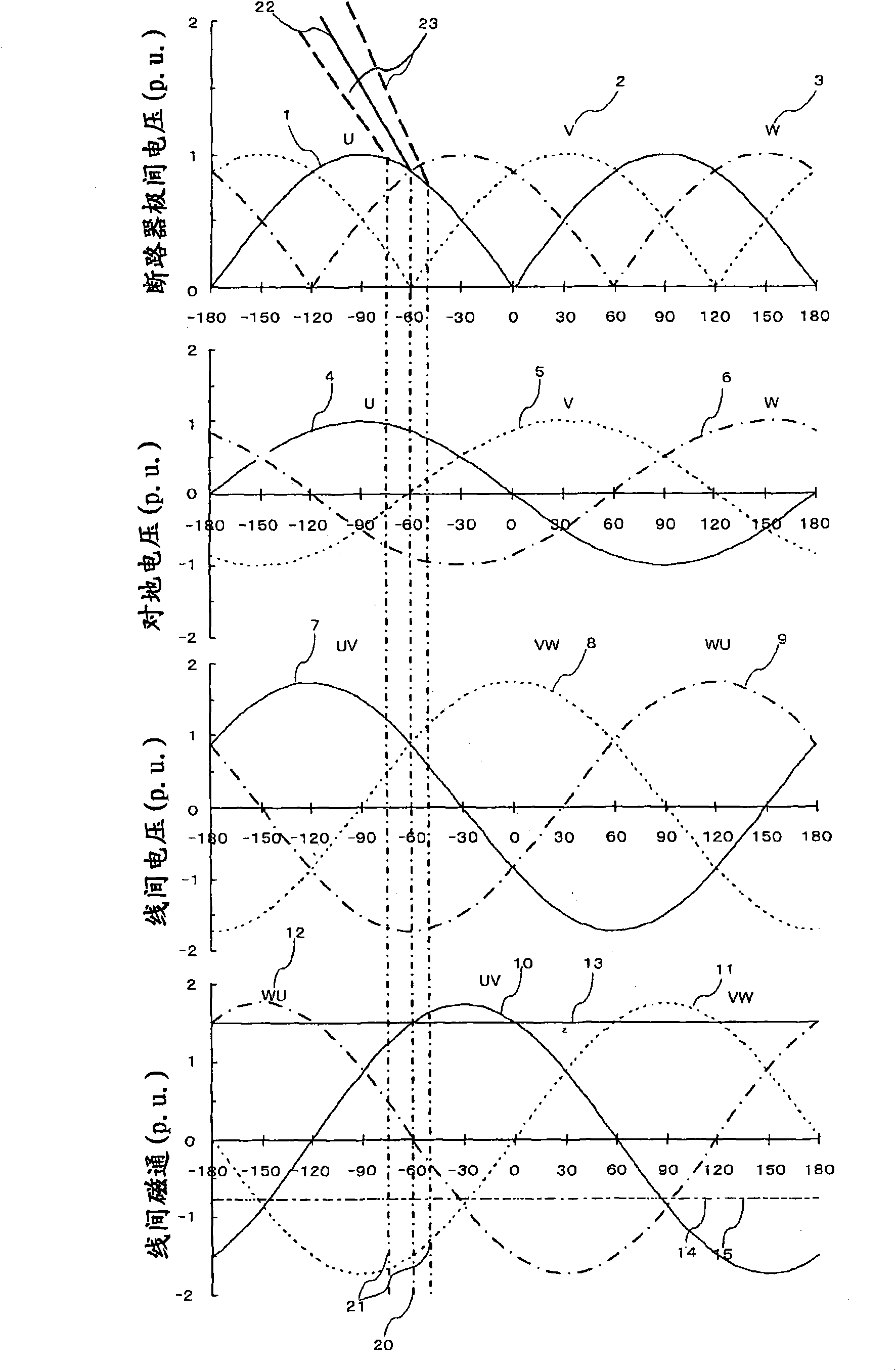
[0098] Next, the following reference Figure 1 to Figure 5 , the configuration and operational effects of the excitation inrush current suppressing device for a transformer according to the first embodiment will be described. in addition, figure 1 It is a block diagram showing the connection relationship between a three-phase transformer, a three-phase circuit breaker, and a connection control device that issues a connection command to the main contacts of each circuit breaker, figure 2 It is a waveform diagram showing the relationship between the pole-to-pole voltage, the power supply phase voltage, the line-to-line voltage, the stable magnetic flux between the lines, and the residual magnetic flux of the circuit breaker used to turn on the transformer.
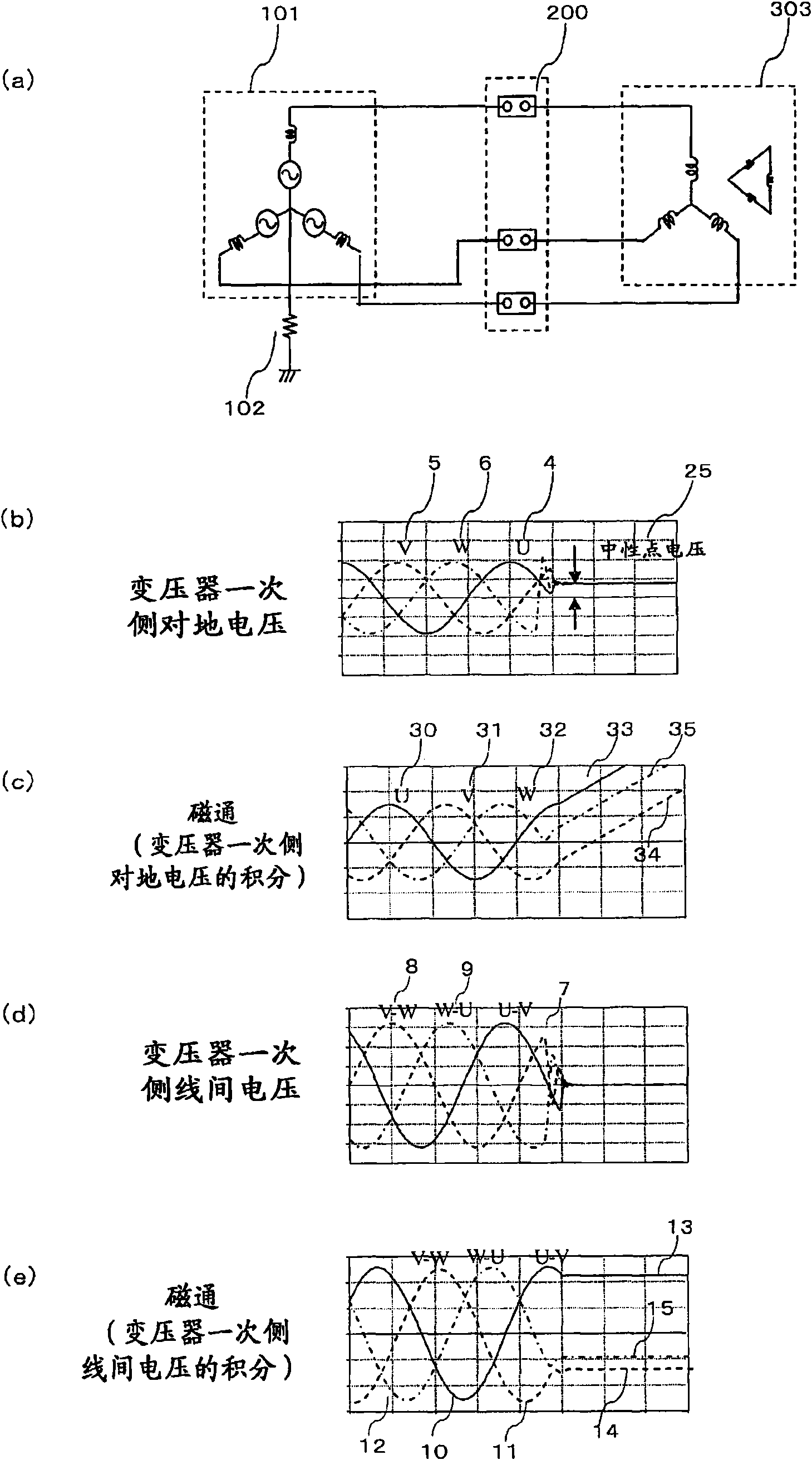
[0099] in addition, image 3 It is a diagram showing the phenomenon that DC voltage is generated in the primary terminal voltage when the non-effectively grounded system transformer is cut off. Figure 4 It is to connect...
no. 2 approach
[0136] Next, the following reference Figure 6 The excitation inrush current suppression device for a transformer according to the second embodiment will be described. in addition, Figure 6 is in figure 2 In the waveform diagram of , the timing at which the circuit breaker 200 is turned on has been changed.
[0137] (2.1. Structure)
[0138] In the second embodiment, since the connection relationship of the three-phase transformer 300, the three-phase circuit breaker 200, and the connection control device 600 is the same as that of the first embodiment described above, it is similar to the first embodiment described above except for the following points. structure is common.
[0139] In the second embodiment, the connection control device 600 is set so that the line with the largest residual magnetic flux among the lines of the three-phase transformer 300 is used as the line where the stable magnetic flux and the residual magnetic flux have the same polarity and magnitud...
no. 3 approach
[0160] Next, the following reference Figure 8 A field inrush current suppression device for a transformer according to a third embodiment will be described. in addition, Figure 8 Shows the phase relationship between the primary Y-side phase voltage and the line-to-line voltage, and the secondary or tertiary Δ-side voltage to ground and the line-to-line voltage.
[0161] (3.1. Structure)
[0162] In the third embodiment, since the connection relationship of the three-phase transformer 300, the three-phase circuit breaker 200, and the connection control device 600 is the same as that of the above-mentioned first embodiment, it is similar to the above-mentioned first embodiment except for the following points. The structure is common.
[0163] In the third embodiment, even if the voltage dividing device is not provided on the primary Y side of the transformer, and the transformer terminal voltage measurement unit 603 cannot measure the transformer terminal voltage on the pri...
PUM
 Abstract
Description
Claims
Application Information
 - R&D
- Intellectual Property
- Life Sciences
- Materials
- Tech Scout
- Unparalleled Data Quality
- Higher Quality Content
- 60% Fewer Hallucinations
Browse by: Latest US Patents, China's latest patents, Technical Efficacy Thesaurus, Application Domain, Technology Topic, Popular Technical Reports.
© 2025 PatSnap. All rights reserved.Legal|Privacy policy|Modern Slavery Act Transparency Statement|Sitemap|About US| Contact US: help@patsnap.com