Electric connector with rotatable interface
What is Al technical title?
Al technical title is built by PatSnap Al team. It summarizes the technical point description of the patent document.
A technology of electrical connectors and interfaces, applied in the direction of flexible/rotatable wire connectors, connections, circuits, etc., can solve the problems of plastic deformation, failure to provide rotation elasticity of the rotating shaft, etc., and achieve good performance effects
Inactive Publication Date: 2011-07-20
SHENZHEN TECHASER TECH
View PDF0 Cites 0 Cited by
Summary
Abstract
Description
Claims
Application Information
AI Technical Summary
This helps you quickly interpret patents by identifying the three key elements:
Problems solved by technology
Method used
Benefits of technology
Problems solved by technology
[0005] However, when the rotating shaft of the above-mentioned USB electrical connector rotates relative to the interface part, the rotating mating part continuously exerts force on the shrapnel, and the shrapnel is repeatedly pressed and rebounded, which is prone to plastic deformation; With the development trend of miniaturization, the small moment of the shrapnel can not provide the elastic force required for the rotation of the shaft
Method used
Image
Click on the blue label to locate the original text in one second.
Reading with bidirectional positioning of images and text.
Examples
Embodiment Construction
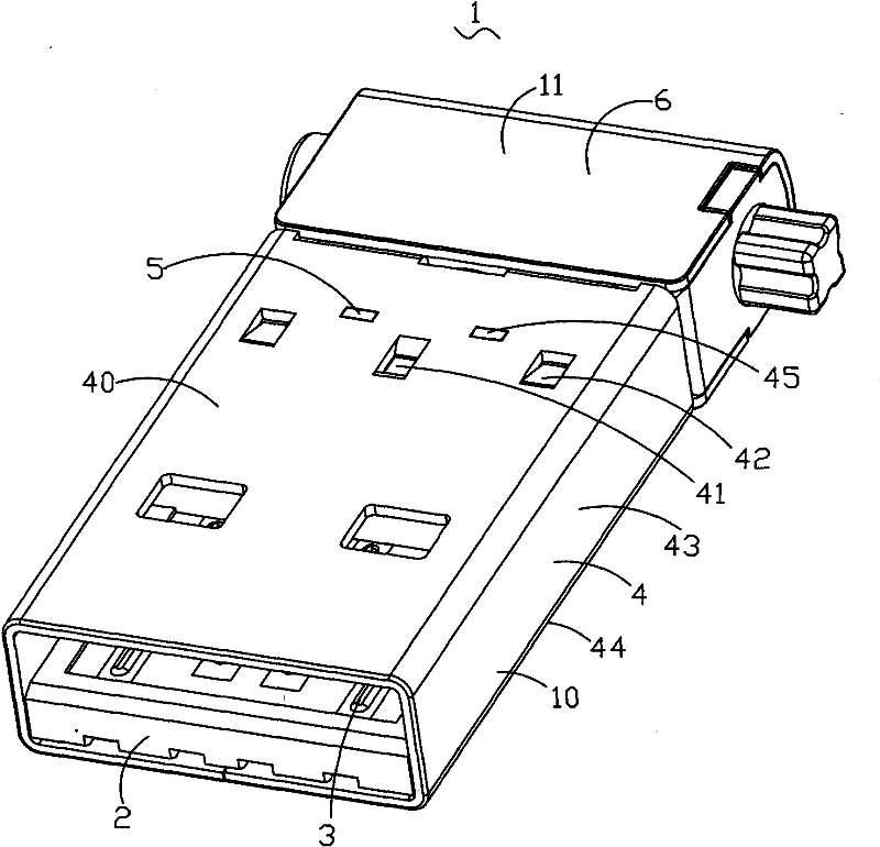
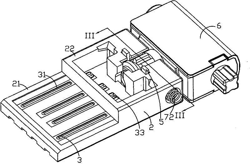
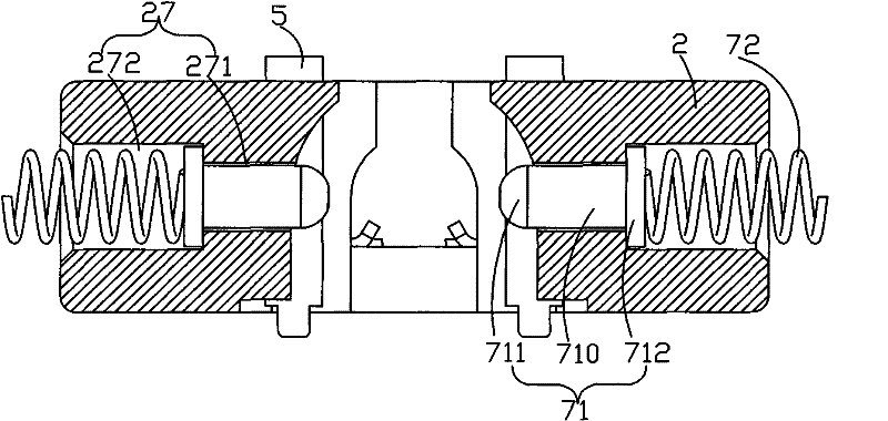
[0018] see Figure 1 to Figure 8 The present invention provides an electrical connector 1 with a rotatable interface, including an interface part 10 and a rotating mechanism 11, wherein the interface part 10 includes an insulating body 2, a group of conductive terminals 3 installed in the insulating body 2, and a set of conductive terminals 3 covered in the insulating body Outer 2 outside the iron shell 4, the rotating mechanism 11 includes a mechanism member 6 with a rotating shaft 62 provided with a circle of hobbing teeth 630, an assembly groove 20 located at the rear of the insulating body 2 for assembling the mechanism member 6, and mounted on the insulating body 2 A pair of elastic parts 7 that rotate in cooperation with the rotating shaft 62 of the mechanism part 6, and a pair of reinforcement parts 5 that strengthen the bonding force between the mechanism part 6 and the insulating body 2.
[0019] Please refer to figure 2 and Figure 7 , the insulating body 2 is gen...
PUM
Abstract
An electric connector with a rotatable interface comprises an interface part and a rotating mechanism, the interface part comprises an insulation body provided with a conductive terminal; and the rotating mechanism comprises a mechanism part with a rotating shaft provided with a circle of hobbing, an assembly groove which is arranged at the rear of the insulation body and used for assembling the rotating shaft of the mechanism part, and a pair of elastic parts which are arranged at the rear part of the insulation body and cooperatively rotates with the rotating shaft of the mechanism part to locate the shaft; wherein, the elastic parts consist of a carrier rod and a spring which abuts on the carrier rod, and the carrier rod props against tooth groove positions between the hobbing on two sides of the rotating shaft. Compared with the prior art, the electric connector with a rotatable interface is characterized in that the cooperation of the elastic parts formed by the combination of the carrier rod and the spring with the rotating shaft of the mechanism part to realize relative rotation of the interface part and the rotating mechanism, thus good elasticity of the elastic parts can be kept by the spring even in frequent use, influencing no service performance.
Description
【Technical field】 [0001] The invention relates to an electrical connector with a rotatable interface, in particular to an electrical connector with a rotatable interface applied to a portable electronic device. 【Background technique】 [0002] The universal serial bus interface (Universal Serial Bus, USB) electrical connector has the characteristics of fast transmission speed, convenient use, hot-swappable support, flexible connection, independent power supply, etc., and is widely used in the electronics industry. , printers, scanners, cameras, flash disks, MP3, mobile phones, digital cameras, mobile hard drives, external optical floppy drives, USB network cards, and almost all external devices. [0003] Therefore, the electronic device connected with the USB electrical connector has a high usage rate. Now some small peripheral devices in the world, such as card readers, network cards or flash drives, etc., the USB connectors are directly attached to the device instead of an...
Claims
Application Information
Patent Timeline
Application Date:The date an application was filed.
Publication Date:The date a patent or application was officially published.
First Publication Date:The earliest publication date of a patent with the same application number.
Issue Date:Publication date of the patent grant document.
PCT Entry Date:The Entry date of PCT National Phase.
Estimated Expiry Date:The statutory expiry date of a patent right according to the Patent Law, and it is the longest term of protection that the patent right can achieve without the termination of the patent right due to other reasons(Term extension factor has been taken into account ).
Invalid Date:Actual expiry date is based on effective date or publication date of legal transaction data of invalid patent.