LED constant current drive circuit with light dimming function

A technology of constant current drive and constant current power supply, applied in the direction of electric lamp circuit layout, light source, electric light source, etc., can solve the problem of low efficiency, and achieve the effect of high efficiency and high dimming precision

Inactive Publication Date: 2012-08-22
西安英洛华微电子有限公司
View PDF3 Cites 0 Cited by
  • Summary
  • Abstract
  • Description
  • Claims
  • Application Information

AI Technical Summary

Problems solved by technology

Therefore, in the case of the same energy consumption, the above-mentioned digital dimming is less efficient than analog dimming

Method used


Image

  • LED constant current drive circuit with light dimming function
  • LED constant current drive circuit with light dimming function
  • LED constant current drive circuit with light dimming function

Examples


Embodiment Construction

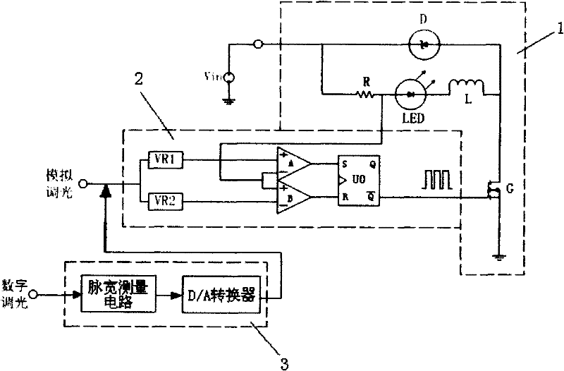
[0015] see figure 1 , The drive circuit includes an LED constant current power supply circuit 1 , an analog LED current regulation circuit 2 and a digital LED current regulation circuit 3 .

[0016] The LED constant current power supply circuit 1 has a power supply circuit composed of DC power supply Vin, LED, energy storage inductor L, current sampling unit and current switch G connected in series and connected in parallel in the series section of LED, energy storage inductor L, and current sampling unit A unidirectional conduction diode D on the top, wherein the current sampling unit can use a sampling resistor R, or a transformer, the LED can be an LED lamp or a plurality of LED lamps connected in series, and the current switch G High-power switching tubes such as MOSFETs can be used.

[0017] The analog LED current regulating circuit 2 includes an upper threshold generation circuit VR2 and a lower threshold generation circuit VR1, a comparator circuit and a pulse width m...


PUM


Abstract

The invention relates to a LED constant current drive circuit with light dimming function, comprising a LED constant current supply circuit, an analog LED current regulating circuit and a digital LED current regulating circuit. The invention has the improvement that the digital LED current regulating circuit comprises a pulse width measuring circuit for a digital light-dimming signal and a D / A converter converting a pulse width attribute output by the pulse width measuring circuit into an analog voltage value. The invention uses the pulse width measuring circuit and the D / A converter to convert a digital light-dimming PWM signal into an analog signal, and then the analog signal is sent to an analog light-dimming input end to carry out analog light dimming; thus, the digital light dimming of the LED constant current drive circuit has the same light-dimming efficiency with analog light dimming, which solves the problem of low efficiency of digital light dimming. Simultaneously, the invention also has the characteristic of high light-dimming precision by further improvement.

Description

technical field [0001] The invention relates to an LED constant current drive circuit, in particular, it is an LED constant current drive circuit with dimming. Background technique [0002] In the prior art, an existing LED constant current drive circuit with dimming such as Figure 4 As shown, it is mainly composed of an LED constant current power supply circuit 1, an analog LED current regulation circuit 2 and a digital dimming interface. The circuit has two modes of dimming, analog and digital. When the analog dimming is working, if the digital dimming input maintains a high level, the AND gate U1 is opened, and a voltage value is input to the analog dimming input, and the voltage value passes through the upper and lower threshold generating circuits VR2 and VR1 respectively. Output the upper threshold and lower threshold voltage, which are used as the threshold voltage of comparators B and A respectively. A current sampling resistor R is set in the LED constant current ...

Claims


Application Information

Patent Timeline
Patent Type & Authority Patents(China)
IPC IPC(8): G06F3/038H05B37/02
Inventor 方建平宋利军郭晋亮杨阳
Owner 西安英洛华微电子有限公司
Why Eureka
Try Eureka