Drilling non-destructive sampling method for deep-buried rock
A non-destructive sampling, deep-buried rock technology, applied in earth-moving drilling, wellbore/well components, etc., can solve the problems of core sample damage, decrease in rock strength, unable to represent rock strength, etc., to eliminate damage and ensure mechanical properties. Effect
- Summary
- Abstract
- Description
- Claims
- Application Information
AI Technical Summary
Problems solved by technology
Method used
Image
Examples
Embodiment 1
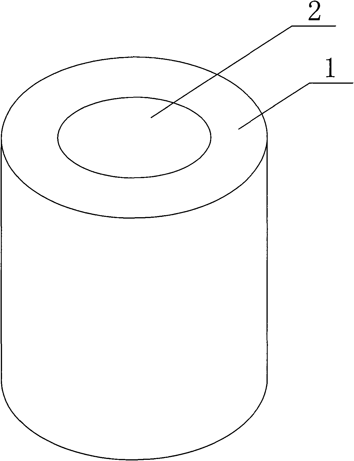
[0017] Embodiment 1: as figure 1 As shown, the specific steps of this embodiment include,
[0018] a. Select the location to be sampled on site, and use a large-sized drill hole to take out the core A1 with a diameter larger than the actual sample diameter. The drill hole diameter is 130 mm, and the drill hole depth is greater than the secondary stress of the surrounding rock in the cavern. In principle, usually greater than 10m-20m after 1 times the hole diameter;
[0019] b. After obtaining the on-site core A, select the core beyond the obvious disturbance zone of the secondary stress of the surrounding rock in the cavern (usually more than one time the diameter of the cave) for casing drilling. In this example, the core obtained in step a A1 was cut off, and the part of the core whose length was more than 1 times the hole diameter was fixed and drilled with conventional equipment to obtain core B2. The diameter of the drill hole was 46 mm, and the core length was 92 mm.
Embodiment 2
[0020] Embodiment 2: as figure 1 As shown, the specific steps of this embodiment include,
[0021] a. Select the location to be sampled on site, and use a large-sized drill hole to take out the core A1 with a diameter larger than the actual sample diameter. The drill hole diameter is 130 mm, and the drill hole depth is greater than the secondary stress of the surrounding rock in the cavern. In principle, usually greater than 10m-20m after 1 times the hole diameter;
[0022] b. After obtaining the on-site core A, select the core beyond the obvious disturbance zone of the secondary stress of the surrounding rock in the cavern (usually more than one time the diameter of the cave) for casing drilling. In this example, the core obtained in step a A1 was cut off, and the core with a length of more than 1 times the hole diameter was fixed and drilled with conventional equipment to obtain core B2. The diameter of the drill hole was 59 mm, and the core length was 118 mm.
Embodiment 3
[0023] Embodiment 3: as figure 1 As shown, the specific steps of this embodiment include,
[0024] a. Select the location to be sampled on site, and use a large-sized drill hole to take out the core A1 with a diameter larger than the actual sample diameter. The drill hole diameter is 150 mm, and the drill hole depth is greater than the secondary stress of the surrounding rock in the cavern. In principle, usually greater than 10m-20m after 1 times the hole diameter;
[0025] b. After obtaining the on-site core A, select the core beyond the obvious disturbance zone of the secondary stress of the surrounding rock in the cavern (usually more than one time the diameter of the cave) for casing drilling. In this example, the core obtained in step a A1 was cut off, and the core with a length of more than 1 times the hole diameter was fixed and drilled with conventional equipment to obtain core B2. The diameter of the drill hole was 59 mm, and the core length was 118 mm.
PUM
 Abstract
Description
Claims
Application Information
 - R&D
- Intellectual Property
- Life Sciences
- Materials
- Tech Scout
- Unparalleled Data Quality
- Higher Quality Content
- 60% Fewer Hallucinations
Browse by: Latest US Patents, China's latest patents, Technical Efficacy Thesaurus, Application Domain, Technology Topic, Popular Technical Reports.
© 2025 PatSnap. All rights reserved.Legal|Privacy policy|Modern Slavery Act Transparency Statement|Sitemap|About US| Contact US: help@patsnap.com

