High-precision microvibration measuring system

A measurement system and micro-vibration technology, applied in measurement devices, measurement of ultrasonic/sonic/infrasonic waves, instruments, etc., can solve problems such as literature reports of micro-vibration measurement systems that have not been seen, and achieve improved measurement accuracy, improved adaptability, and improved reliability. sexual effect

Inactive Publication Date: 2012-05-30
BEIHANG UNIV +1
View PDF5 Cites 1 Cited by
  • Summary
  • Abstract
  • Description
  • Claims
  • Application Information

AI Technical Summary

Problems solved by technology

[0004] At present, there is no literature report on this kind of micro-vibration measurement system at home and abroad.

Method used


Image

  • High-precision microvibration measuring system
  • High-precision microvibration measuring system
  • High-precision microvibration measuring system

Examples


Embodiment Construction

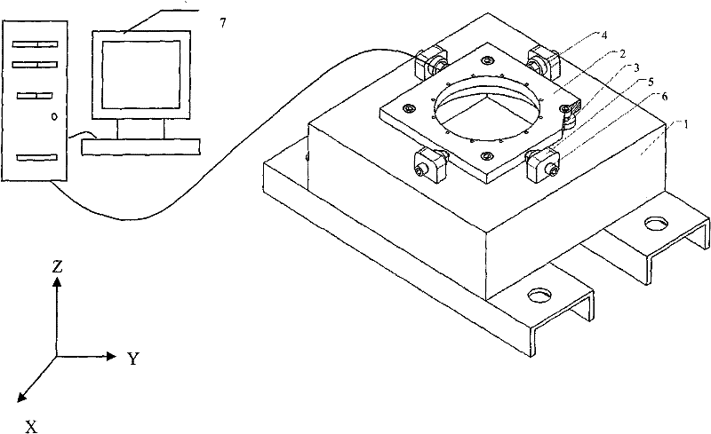
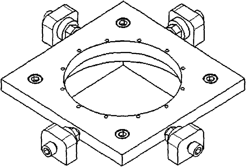
[0023] Such as figure 1 As shown, the base 1, load plate 2, four piezoelectric sensors 3 installed in the vertical direction, four piezoelectric sensors 4 installed in the horizontal direction, four lateral positioning plates 5, eight bolts 6 and Data acquisition and processing system 7; four piezoelectric sensors 3 installed in the vertical direction are located between the upper surface of the base and the lower surface of the load plate, and are pressed by four bolts 6 to measure the vibration force in the Z direction and the X and Y directions Four lateral positioning plates 5 are fixed on the upper surface of the base 1 by screws; four piezoelectric sensors 4 installed in the horizontal direction are fixed on the lateral positioning plate 5 by four bolts 6 and nuts, four The installation direction of the piezoelectric sensor 4 installed in the horizontal direction is in a spatial vertical relationship with the Z axis to ensure that it can measure the vibration torque around...


PUM


Abstract

The invention provides a high-precision microvibration measuring system, which consists of a base, a load pan, eight piezoelectric transducers (four vertically arranged piezoelectric transducers and four horizontally arranged piezoelectric transducer) and a data acquisition and processing system, wherein the vertical piezoelectric transducers are positioned between the load pan and the upper surface of the base and are tightly pressed by bolts; the side piezoelectric transducers are positioned on the periphery of the load pan and are connected with a side positioning plate and the base through blots. The reasonably arranged eight transducers can measure three dynamic forces and three dynamic bending moments of a disturbance source. The disturbance source can be arranged inside or outside the system according to specific requirements. The piezoelectric transducers are connected with the data acquisition and processing system through wires; and the measuring system can precisely measurethe disturbing force of a microvibration source with high reliability.

Description

Technical field [0001] The invention relates to a high-precision micro-vibration measurement system, which can be used for dynamic measurement of vibration signals of a small disturbance load in a spacecraft in six degrees of freedom. Background technique [0002] Most of the current spacecraft are large-scale flexible deployment mechanisms with a large number of optical components, and they have high requirements for pointing accuracy and stability. In addition, in modern spacecraft attitude control systems, reaction wheels, single-frame torque gyroscopes, and solar wing drive mechanisms are important components in the control system. While providing necessary control power, they can also cause harmful vibrations ( For simplicity, the above three systems are collectively referred to as disturbance sources below). These disturbances are mainly caused by flywheel imbalance, bearing disturbance, motor disturbance, motor drive error, etc. Among them, flywheel imbalance is the main ...

Claims


Application Information

Patent Timeline
Patent Type & Authority Patents(China)
IPC IPC(8): G01H11/08
Inventor 赵煜程伟王志旺陈恩涛王和张鹏飞伍时建
Owner BEIHANG UNIV
Why Eureka
Try Eureka