
Pneumatic tire

A technology for pneumatic tires and tires, applied in tire parts, tire treads/tread patterns, vehicle parts, etc., can solve the problems of unsatisfactory drainage, deterioration of handling stability, uneven wear, etc., and achieve good control. Stability, Maintaining Steering Stability, Ensuring Steering Stability

Active Publication Date: 2009-11-25
BRIDGESTONE CORP
View PDF2 Cites 11 Cited by
  • Summary
  • Abstract
  • Description
  • Claims
  • Application Information

AI Technical Summary

Problems solved by technology

[0003] In such tires as described above, in order to enhance water drainage, each inclined groove usually opens to the circumferential groove in the central region of the tread, thereby causing a problem that the acute-angled portion sandwiched between each inclined groove and the circumferential groove Decreased rigidity of the land portion at , resulting in deterioration of handling stability and possible uneven wear
[0004] In the tire of the above-mentioned kind, in the case where the inclined grooves extend in a manner inclined at a large angle with respect to the tire circumferential direction, another problem arises: although the steering stability and durability are improved due to the rigidity of the land portion Uniform wear, but degraded pattern noise and drainage
However, in this case, similarly to the first case described above, there arises a problem that deterioration in steering stability and uneven wear are likely to occur due to deterioration in rigidity of the land portion
[0009] Although the tire disclosed in Japanese Patent Application Laid-Open No. 2006-076349 is excellent in steering stability, the tire has neither a central main groove nor a structure in which inclined grooves open to the central main groove, whereby satisfactory drainage cannot be obtained, Thereby Japanese Patent Application Publication No. 2006-076349 still needs improvement

Method used


Image

  • Pneumatic tire
  • Pneumatic tire
  • Pneumatic tire

Examples


Embodiment 1

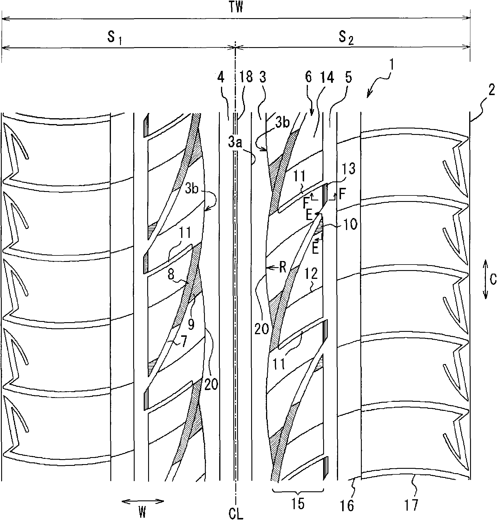
[0120] The tire of Example 1 has such image 3 The tread pattern shown, the sloping groove bottom 8 comprising flat sloping surfaces and as Figure 6 The first chamfer shown in (b), and the tire size of the tire is 195 / 65R15 (tread width TW is 150 mm). Tables 1 to 4 summarize details such as dimensions of the central main groove, side main grooves, steeply inclined grooves, gently inclined grooves, ribbed lands, blocks, etc.

[0121]Since the tire structure other than the tread portion does not need to be changed in the present invention, the tire structure of the tire of Example 1 other than the tread portion is substantially the same as that of a conventional pneumatic tire for passenger cars. The curvature radius R of each arc portion constituting the side wall of the land portion on the side of the central main groove was 165 mm (average).

[0122] Table 1

[0123]

[0124]

[0125] Table 2

[0126] Height of land part (mm)

The width of the land pa...


PUM


Abstract

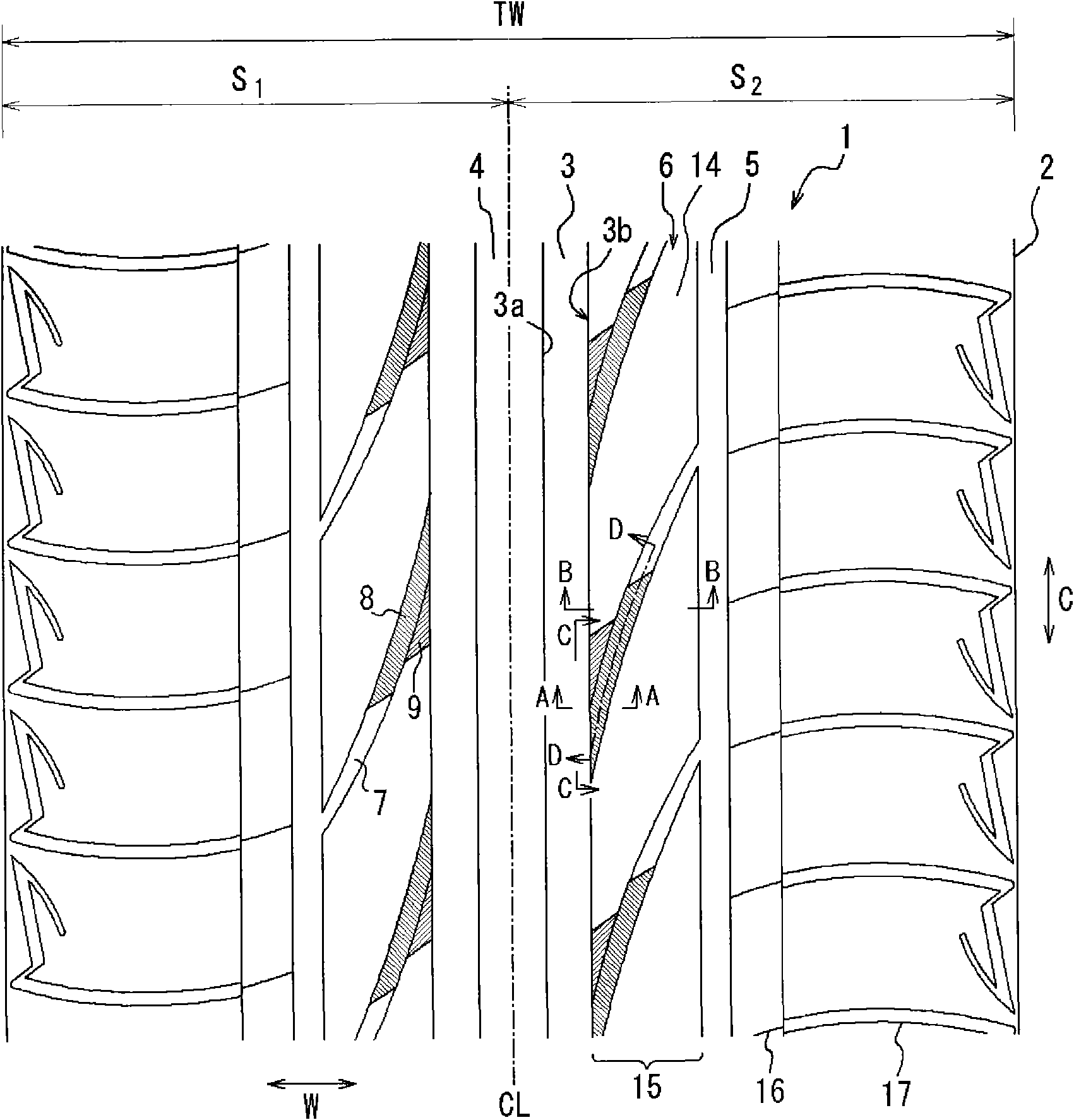
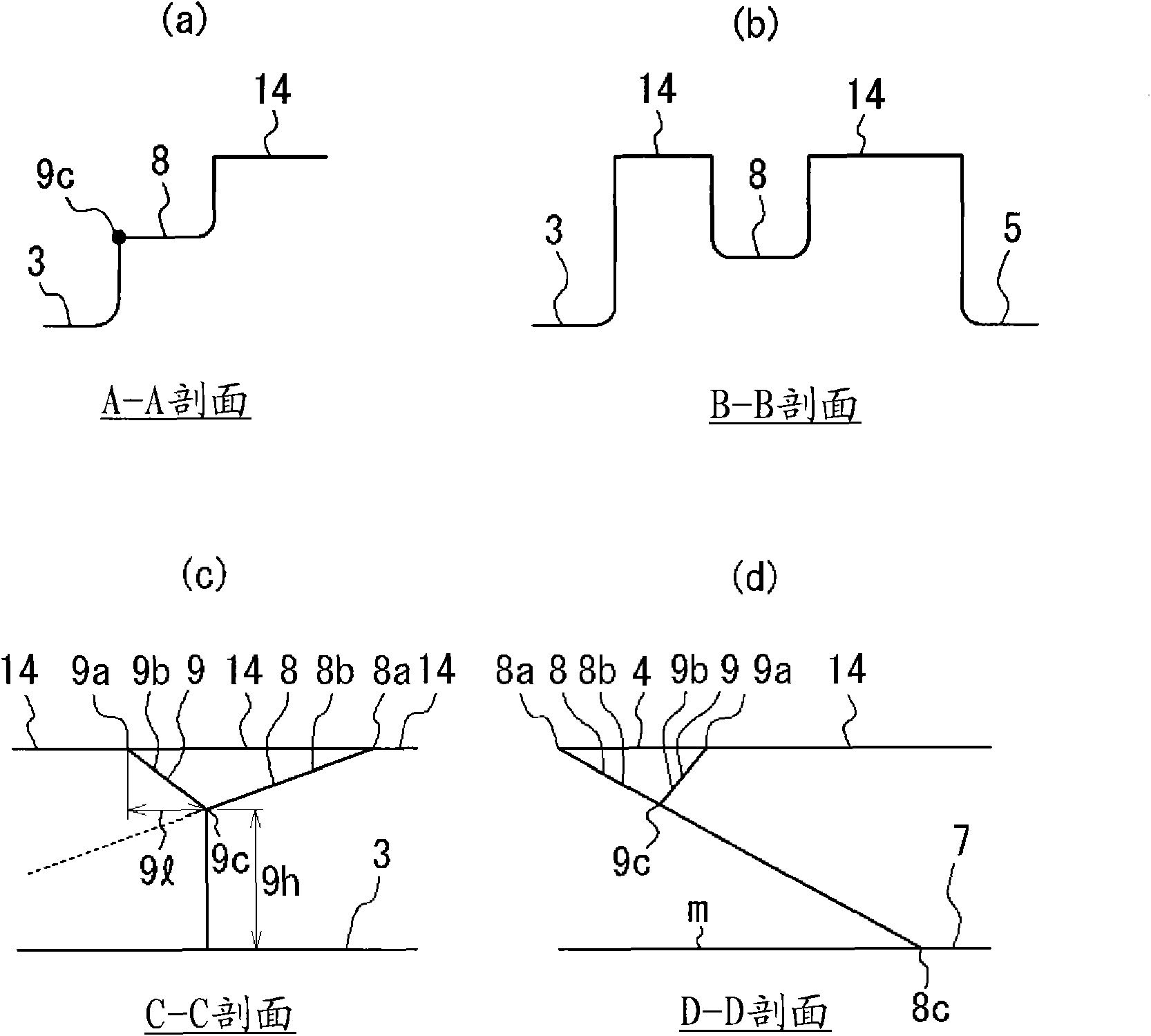
A pneumatic tire that has excellent water discharge ability and driving stability achieved at the same time and in which noise and uneven wear are suppressed. A tread section (1) is divided into two regions by a pattern center, and each half region is provided with a center main groove (3), a side main groove, and steep grooves (7). As a result, a center land section (6) has a block row (15) having a large number of divided substantial blocks (14). In each steep groove (7) is formed a tilt groove bottom (8) where the groove depth gradually increases from the center main groove (3) toward a first side-main-groove (5). A first chamfer (9) where the height of the land section gradually decreases toward the forward end (9c) of the first chamfer is provided at a first acute angle section formed between the center main groove (3) and a steep groove (7). A tilt groove bottom (8) and a first chamfer (9) are adjacent to each other in the lateral direction (W) of the tire.

Description

technical field [0001] The present invention relates to a pneumatic tire, and in particular, to a pneumatic tire excellent in water drainage, handling stability, and uneven wear resistance and capable of reducing noise, thereby improving tire performance with a good balance of the above properties. Background technique [0002] In the pneumatic tire in which the tread portion is provided with circumferential grooves extending in the tire circumferential direction and inclined grooves extending obliquely with respect to the tire circumferential direction, water drainage and Drain towards the side of the tire. [0003] In such tires as described above, in order to enhance water drainage, each inclined groove usually opens to the circumferential groove in the central region of the tread, thereby causing a problem that the acute-angled portion sandwiched between each inclined groove and the circumferential groove Rigidity of the land portion decreases, resulting in deterioratio...

Claims


Application Information

Patent Timeline
Patent Type & Authority Applications(China)
IPC IPC(8): B60C11/11B60C11/04B60C11/13
CPCB60C11/13B60C2011/0388B60C11/1392B60C11/1369B60C11/1384B60C11/0306B60C11/04B60C11/11
Inventor 越智直也
Owner BRIDGESTONE CORP
Learn More