
Temperature control system and temperature control method of machine cabinet

A temperature control system and cabinet technology, applied in ventilation systems, heating methods, lighting and heating equipment, etc., can solve the problems of large impact on heat dissipation efficiency, equipment overcooling, condensation in the inner cavity, etc., to achieve a wide range of temperature adaptation, heat dissipation High reliability and improved heat dissipation efficiency

Inactive Publication Date: 2009-11-25
HUAWEI TECH CO LTD
View PDF0 Cites 10 Cited by
  • Summary
  • Abstract
  • Description
  • Claims
  • Application Information

AI Technical Summary

Problems solved by technology

[0005] In the process of realizing the present invention, the inventors found that there are at least the following problems in the prior art: the heat dissipation efficiency is greatly affected by the ambient temperature. When the ambient temperature is high and the temperature difference between the internal and external circulating airflow is small, the heat transfer effect of the inner wall will drop sharply, which cannot meet the requirements. Equipment Cooling Requirements
When the ambient temperature is too low and the temperature difference between the internal circulating air flow is too large, it will cause condensation in the inner cavity and overcooling of the equipment.

Method used


Image

  • Temperature control system and temperature control method of machine cabinet
  • Temperature control system and temperature control method of machine cabinet
  • Temperature control system and temperature control method of machine cabinet

Examples


Embodiment 1

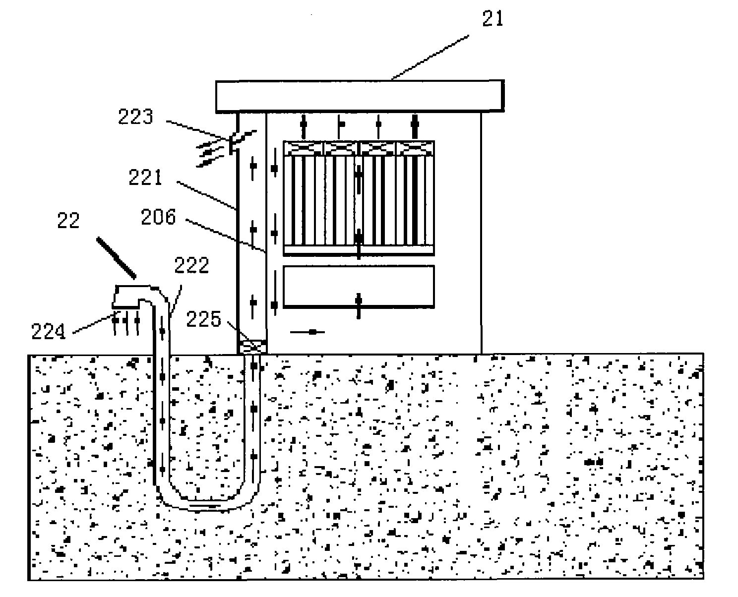
[0027] refer to figure 2 As shown, the cabinet temperature control system of the first embodiment of the present invention includes: a cabinet 21 and a heat dissipation pipeline 22 that communicates with the cabinet and runs through the ground.

[0028] A sealed internal circulation cavity is formed inside the cabinet 21, and the internal circulation is formed by the air drive system of the equipment in the cabinet itself. The circulation cavity in the cabinet is completely sealed, which is beneficial to dustproof, waterproof and humidity control.

[0029] The heat dissipation pipeline 22 includes a first pipeline 221 located in the cabinet and a second pipeline 222 buried underground; the first pipeline includes an air outlet 223 located at the upper part of the cabinet and communicated with ambient air ; The second pipeline includes an air inlet 224 communicating with ambient air. The inner wall of the first pipeline is a heat exchange wall 206, and the outer circulation ...

Embodiment 2

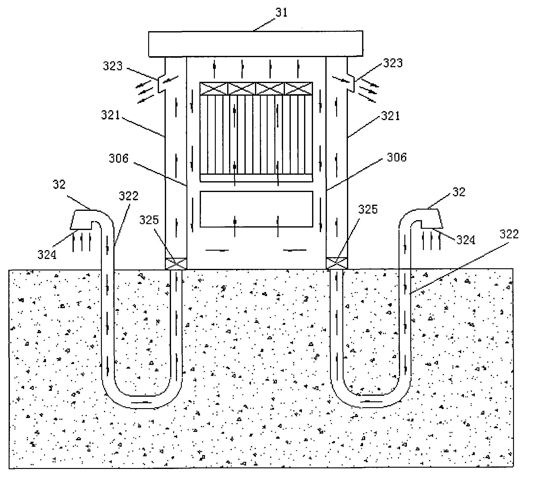
[0040] Such as image 3 As shown, the cabinet temperature control system in the embodiment of the present invention includes a cabinet 31 and two temperature control heat dissipation pipelines 32 that communicate with the cabinet and run through the ground.

[0041] A sealed internal circulation chamber is formed inside the cabinet 31, and the internal circulation is formed by the air drive system of the equipment in the cabinet itself. The circulation cavity in the cabinet is completely sealed, which is beneficial to dustproof, waterproof and humidity control.

[0042] The two heat dissipation pipelines 32 are arranged on the left and right sides of the cabinet respectively; each heat dissipation pipeline 32 includes a first pipeline 321 located in the cabinet and a second pipeline 322 buried underground; the first pipeline The path 321 includes an air outlet 323 located at the upper part of the cabinet and communicates with the ambient air; the second pipeline includes an a...


PUM


Abstract

The embodiment of the invention discloses a temperature control system and a temperature control method of a machine cabinet. The system comprises a machine cabinet and at least one heat dissipation pipeline which is communicated with the machine cabinet and vertically penetrates through the ground. A sealed internal circulation cavity is formed in the machine cabinet, and forms internal circulation through an air driving system of the equipment in the machine cabinet; the heat dissipation pipeline comprises a first pipeline positioned in the machine cabinet and a second pipeline buried underground; the first pipeline comprises an air outlet, is positioned at the upper part of the machine cabinet and is communicated with ambient air; the second pipeline comprises an air inlet communicated with the ambient air; the inner wall of the first pipeline is a heat exchange wall, and the heat exchange between an external circulation cavity formed by the first pipeline and the internal circulation cavity is realized through the heat exchange wall; and the heat dissipation pipeline is provided with at least one air conveying device for driving the air to flow in the heat dissipation pipeline. The embodiment of the invention is suitable for the temperature control of outdoor equipment, in particular for the heat dissipation of the outdoor equipment.

Description

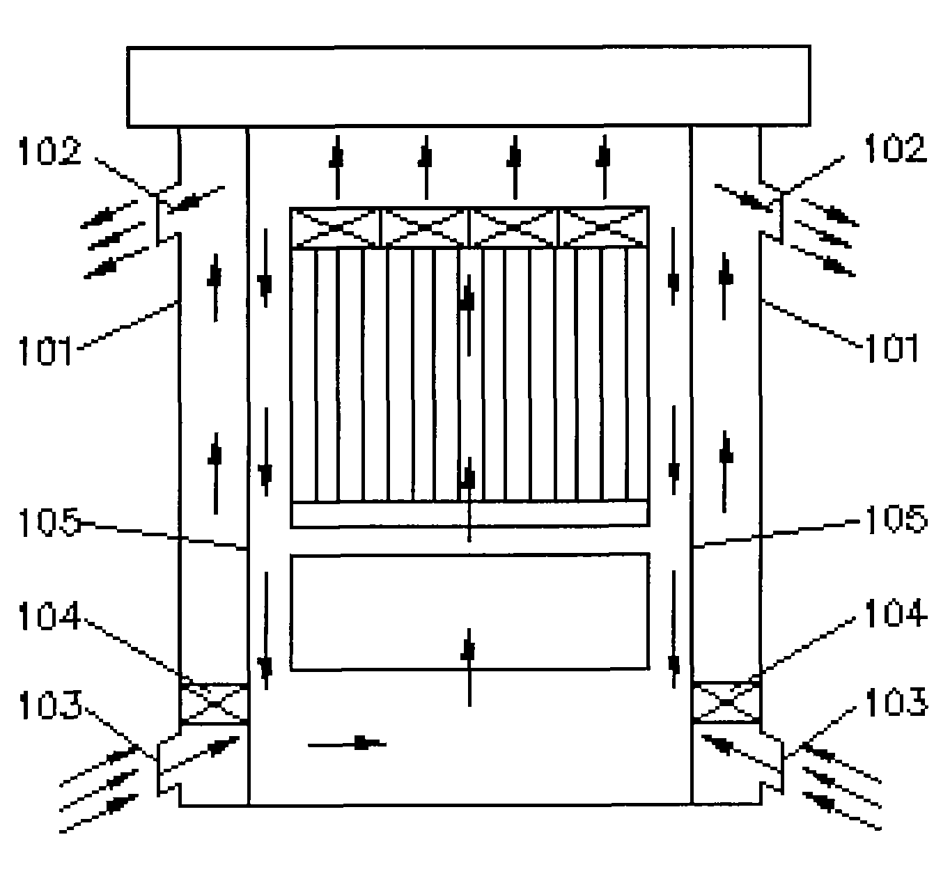
technical field [0001] The invention relates to heat dissipation technology, in particular to a cabinet temperature control system and method. Background technique [0002] Heat-exchange outdoor cabinets and ground source heat pump systems are two common outdoor temperature control devices in the prior art. Among them, the heat-exchange outdoor cabinet uses ambient air as the cold source of the outdoor cabinet, and utilizes ambient air and the internal circulation of the cabinet equipment. The airflow passes through the wall surface to exchange heat and cold to achieve the purpose of heat dissipation. The heat exchange type outdoor cabinet gives full play to the heat dissipation effect of the ambient air temperature, and is mostly used in the heat dissipation of outdoor electronic equipment. The schematic diagram of the structural components of the heat exchange outdoor cabinet is as follows: figure 1 As shown, it includes: two heat dissipation passages 101 located on both...

Claims


Application Information

Patent Timeline
Patent Type & Authority Applications(China)
IPC IPC(8): F24F7/06
Inventor 孔小明姬生钦洪宇平
Owner HUAWEI TECH CO LTD
Learn More