
Calibration method for phase measurement, device and distance measuring apparatus

A calibration device and phase measurement technology, applied in the direction of measuring devices, radio wave measurement systems, electromagnetic wave re-radiation, etc., can solve the problems of long circuit response time, easy mechanical failure, short service life, etc., to reduce costs and strengthen application, the effect of reducing performance requirements

Inactive Publication Date: 2013-04-17
SHENZHEN MILESEEY TECH
View PDF0 Cites 0 Cited by
  • Summary
  • Abstract
  • Description
  • Claims
  • Application Information

AI Technical Summary

Problems solved by technology

[0012] The purpose of the embodiments of the present invention is to provide a calibration method for phase measurement, aiming to solve the problems in the prior art that the circuit has a long response time, is prone to mechanical failure, has a short service life or high cost, and is prone to co-channel interference.

Method used


Image

  • Calibration method for phase measurement, device and distance measuring apparatus
  • Calibration method for phase measurement, device and distance measuring apparatus
  • Calibration method for phase measurement, device and distance measuring apparatus

Examples


Embodiment Construction

[0038] In order to make the object, technical solution and advantages of the present invention clearer, the present invention will be further described in detail below in conjunction with the accompanying drawings and embodiments. It should be understood that the specific embodiments described here are only used to explain the present invention, not to limit the present invention.

[0039] The embodiment of the present invention utilizes the calibration method of dual optical path transmission and single optical path reception, adopts two light wave transmitting devices to generate internal and external optical path signals respectively, and then receives the return signals of the internal optical path signal and the external optical path signal respectively through a signal receiving device, the internal optical path Comparing the phase with the return signal of the external optical path, so as to eliminate the additional phase shift and achieve the purpose of phase error comp...


PUM


Abstract

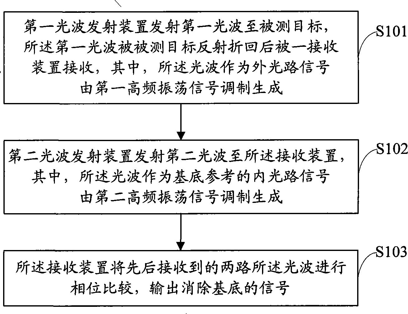
The present invention provides a phase calibration method, device, and equipment. The method comprises the steps of: a first light beam emitter generating a first light-wave into a target object, the first light-wave being reflected at the target object and flying back onto a receiver, wherein the first light-wave, as an external beam path signal, is modulated by a first high-frequency oscillation signal; a second light beam emitter emitting a second light-wave into the receiver, wherein the second light-wave, as an internal beam path signal for fundamental phase reference, is modulated by a second high-frequency oscillation signal; and the receiver performing a phase comparison between received first light-wave and sequentially received second light-wave therein and exporting a measurement signal with fundamental reference eliminated. The present method achieves phase compensation and calibration, thereby reducing the influence of environmental elements, increasing measuring precision, and thus reducing system cost.

Description

technical field [0001] The invention belongs to the field of photoelectric distance measurement, and in particular relates to a phase measurement calibration method, device and distance measurement equipment. Background technique [0002] With the rapid development of semiconductor lasers and digital circuits since the 1980s, long-distance and high-precision laser ranging technology has become more and more widely used in electric power, water conservancy, communications, environment, construction, police, fire protection, blasting, and navigation. In fields such as railways, military anti-terrorism, etc., phase laser ranging products with millimeter-level measurement accuracy have gradually become dominant in short-range laser ranging within 200 meters. The laser distance measuring device based on the principle of phase difference measurement uses a modulated laser beam to irradiate the measured target. The beam is reflected by the measured target and then turned back. The ...

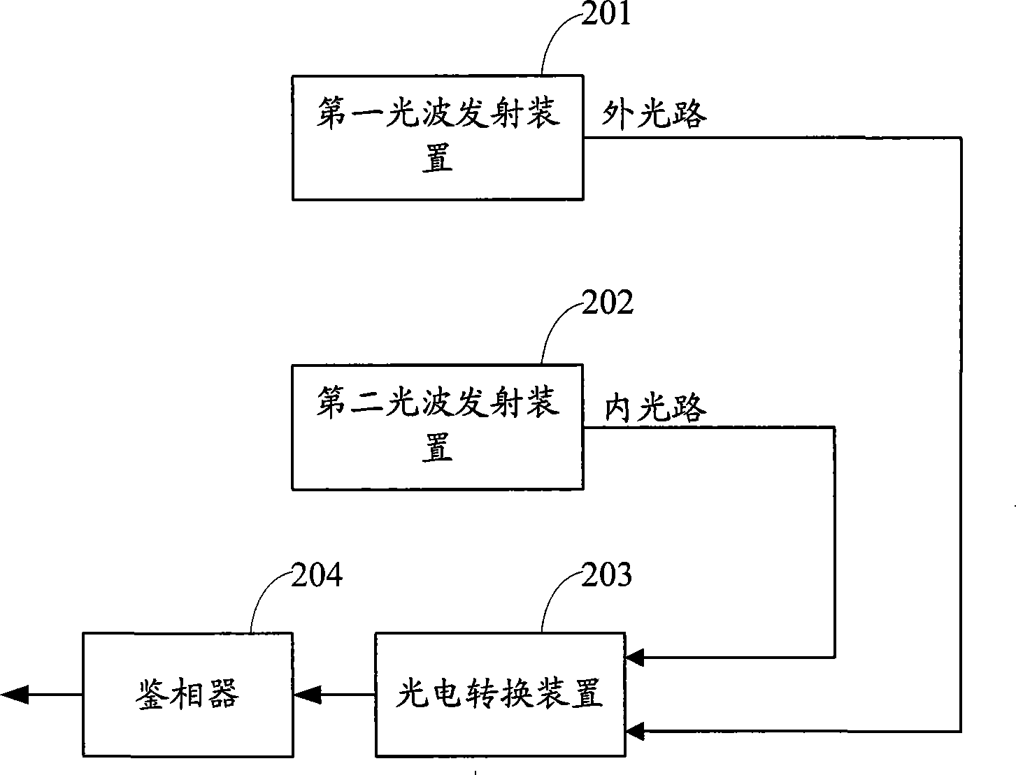
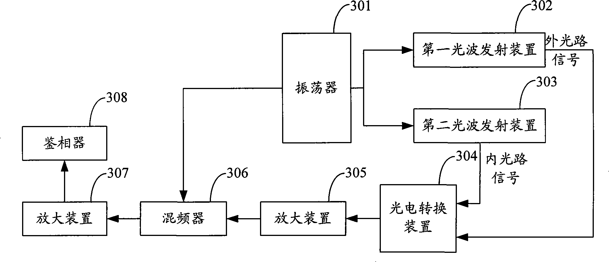
Claims


Application Information

Patent Timeline
Patent Type & Authority Patents(China)
IPC IPC(8): G01S7/497G01S17/32
CPCG01S7/497G01S17/36
Inventor 杜鑫伍昕侴智
Owner SHENZHEN MILESEEY TECH
Learn More