
Tunable fiber F-P cavity filter

A filter and optical fiber technology, applied in the field of new tunable fiber F-P cavity filter and wavelength demodulation, can solve the problems of unstable wavelength-voltage relationship of F-P cavity filter, affecting the performance of F-P cavity filter, optical performance drift, etc. , to achieve the effect of low cost, stable work and good repeatability

Inactive Publication Date: 2009-11-11
INST OF SEMICONDUCTORS - CHINESE ACAD OF SCI
View PDF0 Cites 17 Cited by
  • Summary
  • Abstract
  • Description
  • Claims
  • Application Information

AI Technical Summary

Problems solved by technology

This is because the ε term in the relationship between the displacement and voltage of piezoelectric ceramics is related to the temperature and heating history, so the temperature will cause nonlinearity and hysteresis loops in the relationship between displacement and voltage of piezoelectric ceramics, which will affect Performance of F-P cavity filter
[0017] In addition, the fiber end face and the cavity of the F-P cavity filter are mostly formed by stacking multi-layer films, and the temperature change will have a great influence on the transmission interference characteristics of the filter, causing the transmission center wavelength to drift with temperature, resulting in the wavelength voltage of the F-P cavity filter The relationship is unstable, and its optical performance will be degraded due to the drift of the central wavelength and the increase of the transmission spectral width due to time aging.

Method used


Image

  • Tunable fiber F-P cavity filter
  • Tunable fiber F-P cavity filter
  • Tunable fiber F-P cavity filter

Examples


Embodiment Construction

[0045] In order to make the object, technical solution and advantages of the present invention clearer, the present invention will be described in further detail below in conjunction with specific embodiments and with reference to the accompanying drawings.

[0046] The present invention adopts the F-P cavity filter for temperature control treatment, uses materials with negative thermal expansion coefficient to reduce the influence of temperature on the F-P filter, and strictly seals and heat-insulates the F-P cavity filter, so that the F-P provided by the present invention The cavity filter has a wide spectrum range and narrow tuning precision, and has the advantages of good repeatability, low cost and practicality.

[0047] Such as figure 2 as shown, figure 2 The structure schematic diagram of the tunable optical fiber F-P cavity filter provided by the present invention, this F-P cavity filter comprises:

[0048] An encapsulating box 1 made of metal or ceramic material;

...


PUM


Abstract

The invention discloses a tunable fiber F-P cavity filter, which comprises a packaging box (1), a semiconductor refrigeration device (12), a structural block (4), piezoelectric ceramics (10), a temperature measurement element (8), a heat-resistant material (9), a jacket (6), a first optical fiber (2), a second optical fiber (13) and an F-P cavity, wherein the packaging box (1) consists of a metal or ceramic material; the semiconductor refrigeration device (12) is fixed in the packaging box (1); the structural block (4), the piezoelectric ceramics (10), the temperature measurement element (8) and the heat-resistant material (9) are fixed on the semiconductor refrigeration device (12); the jacket (6) is sealed through an epoxy resin pasting material and is fixed on the structural block (4) provided with a spherical through hole; the first optical fiber (2) is fixed in the jacket (6) through a first optical-fiber contact pin (5); the second optical fiber (13) is fixed in the jacket (6) through a second optical-fiber contact pin (7); and the F-P cavity is formed by the first optical fiber (2) and the second optical fiber (13) of which the end faces are coated with films. The tunable fiber F-P filter provided by the invention has the advantages of high resolution, large dynamic range, fast response, stable work and the like, and the performance of the F-P filter is greatly improved.

Description

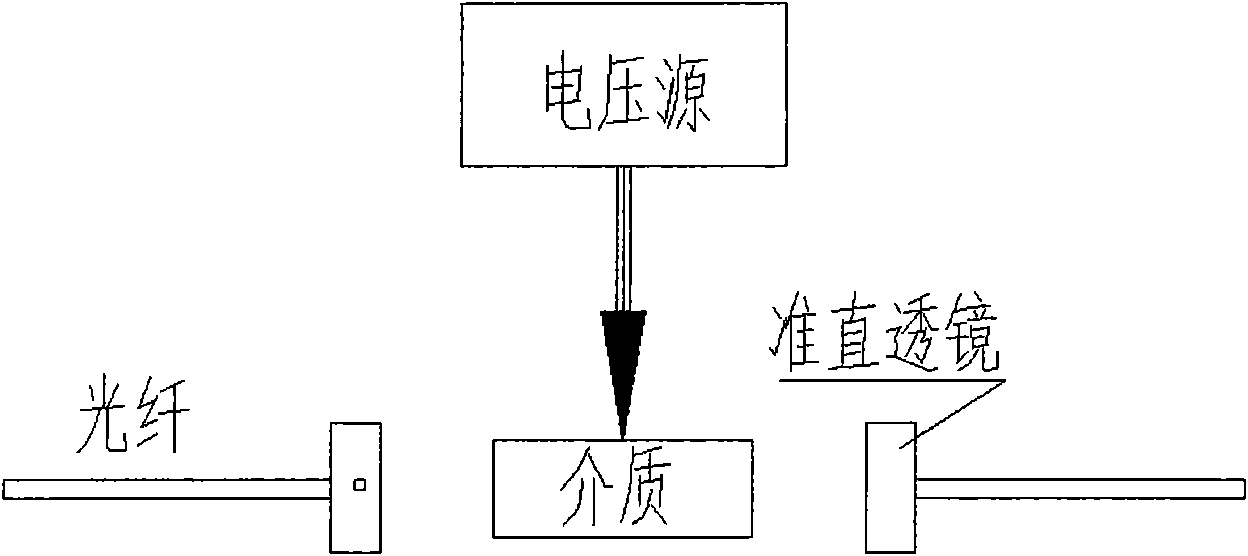
technical field [0001] The invention relates to the technical fields of optical fiber sensing and optical communication, in particular to a novel tunable optical fiber F-P cavity filter with high resolution and good wavelength stability, which is mainly used in wavelength demodulation of wavelength modulation sensors. Background technique [0002] F-P cavity filter is one of the important devices in the field of optical fiber sensing technology and optical communication. The typical structure of the existing F-P cavity filter is as follows figure 1 As shown, it is mainly composed of an F-P cavity composed of two optical fibers coated with a reflective film on the end face and a piezoelectric ceramic used to control the distance between the end faces of the optical fiber (ie, the length of the cavity). The piezoelectric ceramics will deform with the control signal, thereby controlling the cavity length of the F-P cavity filter, so that the transmission wavelength of the F-P ...

Claims


Application Information

Patent Timeline
Patent Type & Authority Applications(China)
IPC IPC(8): G02B6/34G02B26/00G02B26/08
Inventor 秦海琨李芳刘育梁
Owner INST OF SEMICONDUCTORS - CHINESE ACAD OF SCI
Learn More