Sewing machine

A sewing machine and machine frame technology, which is applied to sewing machine components, sewing machine needle holders, sewing equipment, etc., can solve problems such as increased resistance, embroidery pattern damage, and difficulty in stabilizing immediately

Inactive Publication Date: 2009-11-11
BARUDAN KK
View PDF2 Cites 0 Cited by
  • Summary
  • Abstract
  • Description
  • Claims
  • Application Information

AI Technical Summary

Problems solved by technology

[0022] However, in the case of increasing the acting force, the following problem will occur on the contrary: that is, the resistance to the driving force of the solenoid when the engaging member is disengaged from the engaging part of the needle bar is enhanced, so that the engaging member The disengagement speed of the hook part from the needle bar is slowed down
In this way, there is a problem that the needle bar repeatedly descends and rises near the top dead center, and it is difficult to stabilize immediately after reaching the top dead center.
[0026] In this way, the needle bar moves up and down repeatedly after reaching the top dead center and is unstable at a certain position of the top dead center. The hooking part is engaged, and the knocking part in the lifting body cannot be correctly engaged with the hanging part of the needle bar after reaching the top dead center and then descending. There is only the lifting body without the needle The rod falls, and the scheduled sewing cannot be carried out, causing the embroidery pattern to be destroyed.

Method used


Image

  • Sewing machine
  • Sewing machine
  • Sewing machine

Examples


Embodiment Construction

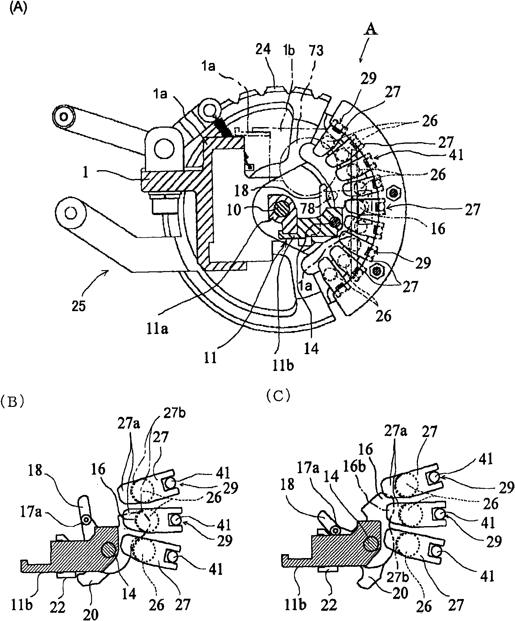
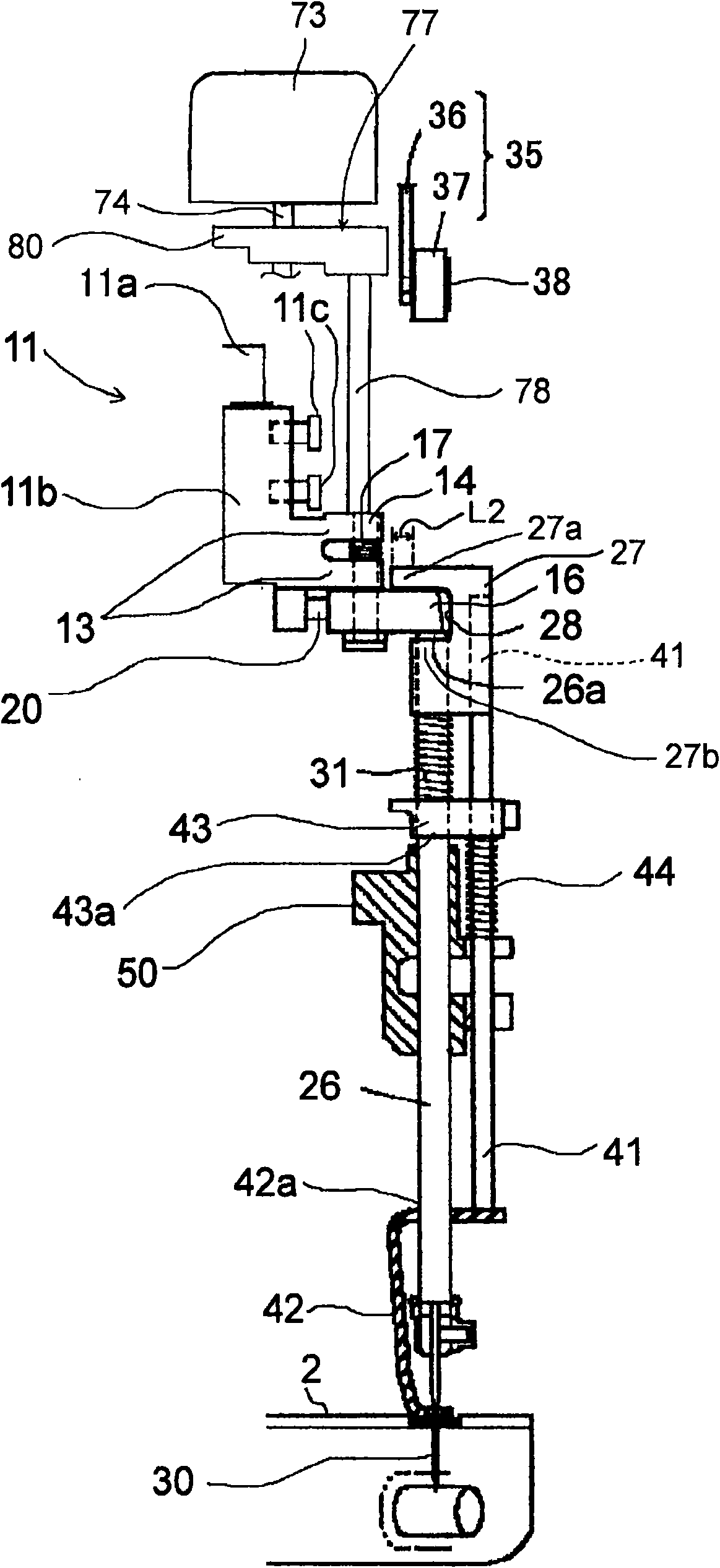
[0054] Embodiments of the present invention will be described below using the drawings. exist figure 1 , figure 2 Among them, frame 1, thread take-up lever 3, parts 24-31 related to the needle bar, parts 35-38 related to the needle bar stopper, parts 41-44 related to the cloth presser foot, parts related to the lifting body Parts 5-22, parts related to the jump mechanism 70 (however, the novelties added in the following explanations related to parts such as the hooking part 27 of the needle bar, the second engaging claw 16b of the lifting body, and the action part 78 The configuration of the technical solution (component configuration, combination and function, etc.) except for the description of related matters) represents an example of the component configuration of a conventionally known known sewing machine. figure 1 An example of the same operation and function as the sewing machine shown in .

[0055] Reference numeral 1 denotes a frame (also referred to as a bottom ...


PUM


Abstract

An object of the present invention is to provide a sewing machine that naturally enables performing normal sewing work, and that enables skipping a stitch during the sewing work, and furthermore, another object is to provide a sewing machine that enables causing a latching portion and an engaging device of the needle bar to be accurately engaged and disengaged when skipping the stitch during the sewing work. An operating member return spring is provided between the operating member and the frame; and the operating member return spring is formed such that, in a process that upon supplying powerto the solenoid the latching portion is being driven from the engaging position to the retreated position, a spring force of the operating member return spring is not, or only weakly exerted on the operating member while the latching portion is located between the engaging position and the vicinity of a departing point where the latching portion starts to be disengaged, and that the spring forceis relatively strongly exerted on the operating member while the latching portion is located between the vicinity of the departing point and the retreated position, so that resilient force is stored in the operating member return spring with the movement of the operating member.

Description

technical field [0001] The invention relates to a sewing machine, in particular to a sewing machine capable of skipping stitches during sewing. Background technique [0002] Conventionally, sewing machines capable of skipping stitches during sewing are widely known. For example, there is a sewing machine shown in Patent Document 1 as such a sewing machine. The sewing machine of patent document 1 has the following structure. [0003] This sewing machine is provided with: the upper part is provided with the needle bar of hooking part (hanging part) and is equipped on the head frame freely up and down, and is driven by the main shaft and is equipped with and is equipped with to move up and down freely toward the direction parallel to the above-mentioned needle bar, The above-mentioned elevating body is equipped with an engaging part (engaging claw), which is always engaged with the engaging part of the above-mentioned needle bar in order to make the needle bar move up and dow...

Claims


Application Information

Patent Timeline
Patent Type & Authority Applications(China)
IPC IPC(8): D05B55/14D05B55/10
Inventor 春日井启介
Owner BARUDAN KK
Why Eureka
Try Eureka