
Gating design method for die-casting formation of large thin-wall element with narrow flange

A large thin-walled parts, die-casting molding technology, applied in the field of bidirectional tangential cycloidal gate design, can solve the problems of easy generation of flow marks, melt pressure and speed attenuation, great difficulty in design and manufacture, etc., to achieve guaranteed Dimensional and shape accuracy, reduced flow power loss, effects of reduced die casting defects

Inactive Publication Date: 2009-11-04
FUJIAN UNIV OF TECH
View PDF0 Cites 0 Cited by
  • Summary
  • Abstract
  • Description
  • Claims
  • Application Information

AI Technical Summary

Problems solved by technology

However, the mold design and manufacture are very difficult
Existing problems include: too thin or uneven wall thickness is prone to defects such as flow marks, incomplete corners or cracks, cold shuts, and slag inclusions. The quality stability of products produced by molds designed according to traditional methods is poor, and it is difficult to meet the requirements of related technologies. Require
In this way, defects such as cold shut, under-injection, cracks, and pores will appear at the front of the melt, resulting in an increase in the reject rate
[0006] Therefore, in order to improve the structure of the gating system, it is necessary to take measures to solve the problem of the large attenuation of the melt pressure and velocity due to the existence of the flange. At the same time, it is necessary to reduce the structure of the gate in the design of the die-casting process, thereby reducing the flow of the melt stress and power loss

Method used


Image

  • Gating design method for die-casting formation of large thin-wall element with narrow flange
  • Gating design method for die-casting formation of large thin-wall element with narrow flange
  • Gating design method for die-casting formation of large thin-wall element with narrow flange

Examples


Embodiment 1

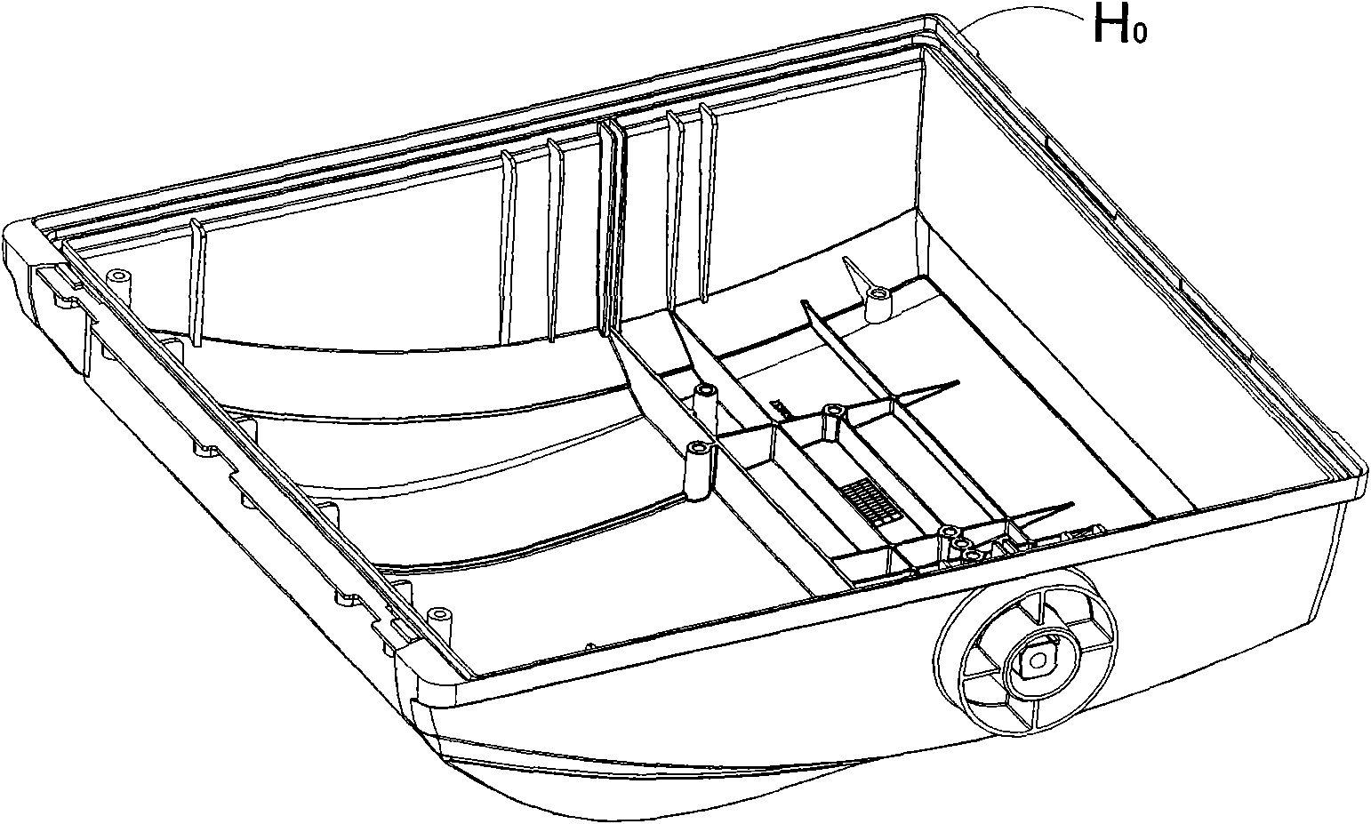
[0051] Such as Figure 2a and 2b As shown, this embodiment takes a lampshade aluminum alloy die-casting part of a certain specification as an example. The outer dimension of the die-casting part is 405mm×385mm×164mm, the average wall thickness is 2.0mm, and the thinnest part is 1.5mm. Flange width H 0 =5mm, the density of the melt ρ=2.4g / cm 3 , the mass of molten metal passing through the inrunner m=1580g, the injection speed v=2500-3000cm / s, and the filling time t=0.014-0.020s.

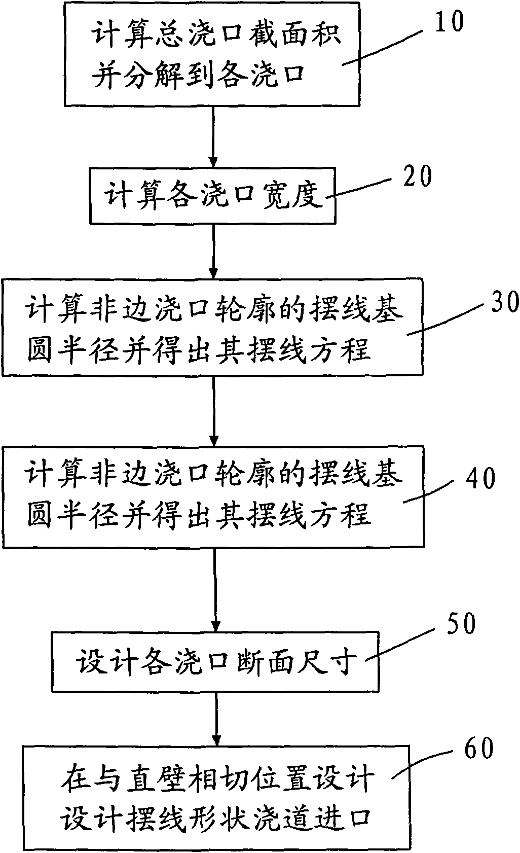
[0052] Step 10. Calculate the cross-sectional area A of the ingate:

[0053] A=m / ρvt=1580 / (2.4×2500×0.020)=13.16cm 2

[0054] Such as image 3 As shown, set 8 gates, and set each gate A i The area is A 1 , A 2 ,...,A 8, decompose the total gate cross-sectional area A into each gate. The decomposition method is to increase sequentially from both ends to the middle according to the total gate number, and the increase in adjacent linear dimensions does not exceed 15%, and the cross-sectional a...


PUM

PropertyMeasurementUnit
sizeaaaaaaaaaa
thicknessaaaaaaaaaa

Abstract

The invention provides a gating design method for die-casting formation of a large thin-wall element with narrow flange. The method comprises the following steps: step 10, calculating the section area of a mater gate, and dividing the section area value to each gate so as to obtain the section area of each gate; step 20, calculating the width of each gate; step 30, calculating cycloid base radiuses of non-edge gate outlines according to the gate widths so as to obtain the cycloid equation of each non-edge gate outline; step 40, calculating cycloid base radiuses of two-edge gate outlines according to the gate widths so as to obtain the cycloid equation of the two-edge gate outlines; and step 50, designing the gate cross dimensions according to the section areas of the gates and the outline sizes. The method changes the conventional straight-line-form gate into a continuous curve form without point of discontinuity, takes advantage of the isochronism of the cycloid to reduce the flowing power loss of a fused mass, causes die-casting fronts to simultaneously reach a destination, and effectively reduces the die-casting defects.

Description

【Technical field】 [0001] The invention relates to a method for designing a runner in a die-casting mold, in particular to a method for designing a two-way tangential cycloidal gate for die-casting of a large thin-walled part with a narrow flange. 【Background technique】 [0002] Large thin-walled die-casting parts, especially large-scale thin-walled box-type die-casting parts, are important parts used for load bearing, rotation, lighting and other occasions, such as electric cutting machine gearbox, air-cooled direct injection diesel engine body, light alloy intake manifold Tubes, etc. are all such parts. The maximum size of this type of die-casting can reach more than 400mm, and the thickness can reach 1.5mm or less. The maximum size of the die-casting mold often reaches more than 800mm. [0003] Large thin-walled box-type die-casting parts have the characteristics of complex structure, high precision requirements, high performance requirements for bearing alternating loads...

Claims


Application Information

Patent Timeline
Patent Type & Authority Applications(China)
IPC IPC(8): B22D17/22
Inventor 王乾廷陈鼎宁林永南王火生翁其金陈文哲
Owner FUJIAN UNIV OF TECH
Learn More