Backlight module and an optical target thereof

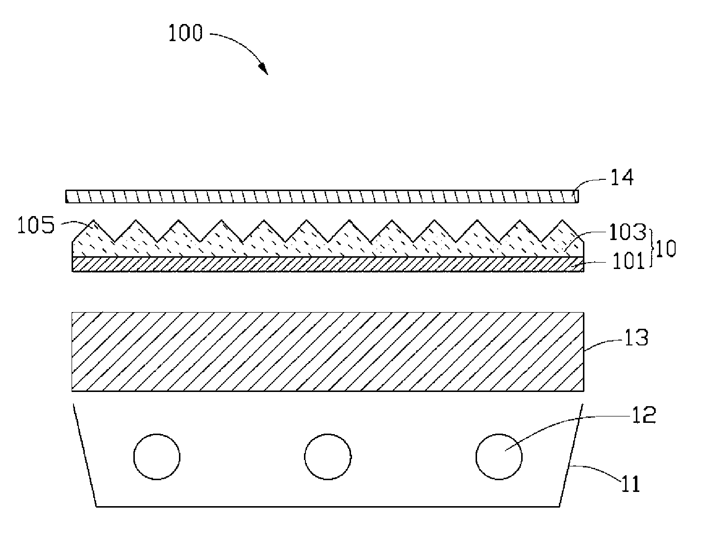
A backlight module and optical board technology, applied in optics, optical components, nonlinear optics, etc., can solve the problems of increasing the number of light interfaces, reducing the brightness of light emitted by the backlight module 100, increasing the loss of light transmission interfaces, etc.

Inactive Publication Date: 2009-10-21
HONG FU JIN PRECISION IND (SHENZHEN) CO LTD +1
View PDF0 Cites 1 Cited by
  • Summary
  • Abstract
  • Description
  • Claims
  • Application Information

AI Technical Summary

Problems solved by technology

However, when the light is transmitted in the upper diffusion sheet 14, part of the light will be absorbed by the upper diffusion sheet 14 and cause part of the light loss; and the use of the upper diffusion sheet 14 will also increase the number of interfaces in the transmission process of the light, thereby increasing the light transmission. Therefore, the use of the upper diffusion sheet 14 will reduce the utilization rate of light and reduce the brightness of the backlight module 100.

Method used


Image

  • Backlight module and an optical target thereof
  • Backlight module and an optical target thereof
  • Backlight module and an optical target thereof

Examples


Embodiment Construction

[0015] The optical plate of the present invention will be further described in detail below with reference to the drawings and embodiments.

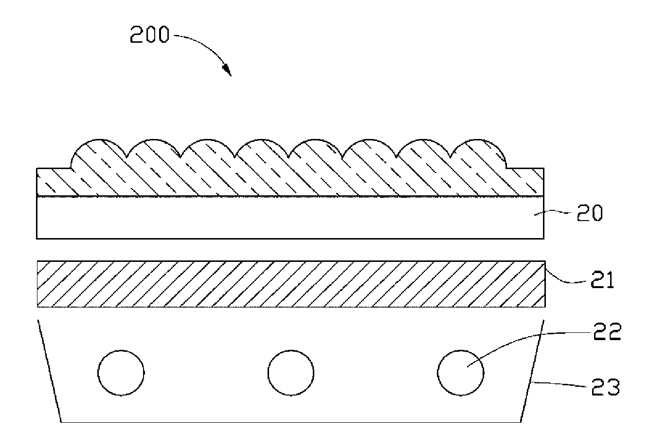
[0016] See image 3 , shows the backlight module 200 of the preferred embodiment 1 of the present invention, which includes an optical plate 20, a diffuser plate 21 disposed on one side of the optical plate 20, a plurality of light sources 22 and a frame 23 for accommodating the plurality of light sources 22 The light emitted by the light source 22 enters the diffuser plate 21 directly or reflected by the frame 23 , diffuses through the diffuser plate 21 and then enters the optical plate 20 for focusing.

[0017] See Figure 4 , the optical plate 20 is composed of a transparent body, and the transparent body includes a first surface 201 and a second surface 203 opposite to the first surface 201 . The first surface 201 has a plurality of elongated arc-shaped grooves 202 , and the second surface 203 has a plurality of elongated arc-shape...


PUM

PropertyMeasurementUnit
thicknessaaaaaaaaaa

Abstract

The invention relates to an optical target formed by a transparent body which comprises a first surface and a second surface opposite to the first surface; wherein the first surface is provided with a plurality of long strip arc sockets and the second surface is provided with a plurality of strip arc bulges; the extending direction of a plurality of strip arc bulges on the second surface intersects with the extending direction of a plurality of long strip arc sockets on the first surface. The optical target has the advantages of increasing the effective utilization of light and uniform light-emitting.

Description

technical field [0001] The invention relates to a backlight module and its optical board, in particular to a backlight module for liquid crystal display and its optical board. Background technique [0002] See figure 1 and figure 2 , shows an existing direct-lit backlight module 100, which includes a frame 11, a plurality of light sources 12 arranged inside the frame 11, a diffusion plate 13 arranged above the light sources 12 and covering the frame 11, and A prism sheet 10. Wherein, the diffusion plate 13 generally contains scattering particles for diffusing light. The prism sheet 10 includes a transparent substrate 101 and a prism layer 103 formed on the transparent substrate 101 . The prism layer 103 has a plurality of elongated V-shaped protrusions 105 . [0003] When in use, the light generated by the plurality of light sources 12 enters the diffuser plate 13 and is uniformly diffused, then continues to enter the prism sheet 10, and under the action of the elongat...

Claims


Application Information

Patent Timeline
Patent Type & Authority Applications(China)
IPC IPC(8): G02F1/13357G02B1/04G02F1/1335
CPCG02F1/133606G02F2001/133607G02F1/133607
Inventor 章绍汉
Owner HONG FU JIN PRECISION IND (SHENZHEN) CO LTD
Why Eureka
Try Eureka