High-low pressure guide valve

A low-pressure, valve cavity technology, applied in the direction of valve lift, valve details, valve device, etc., can solve the problems of sealing failure, poor sensitivity, slow response speed, etc. Effect

Active Publication Date: 2013-05-01
SICHUAN HUAYU PETROLEUM DRILLING & PRODION EQUIP
View PDF1 Cites 0 Cited by
  • Summary
  • Abstract
  • Description
  • Claims
  • Application Information

AI Technical Summary

Problems solved by technology

The core component of all control systems is the sensing pilot valve (Pilot). Since the piston valve body is not suitable for high-pressure applications in oil and gas wellheads, and its cylindrical spool has high requirements for the verticality of the two sealing surfaces, the deviation of the spool It will lead to sealing failure. At present, the sliding valve structure is generally adopted at home and abroad, such as figure 1 and figure 2 As shown, the spool of the pilot valve is installed in the through hole in the valve body. One end of the spool is the pressure detection end, and the other end is installed with an elastic reset element. There are two "O"-shaped sealing elements on the spool, and two " There is a fluid channel between the O”-shaped sealing elements. When the pressure at the pressure detection end exceeds the predetermined value, under the joint action of the elastic reset element and the pressure, the valve core moves to connect the inlet and outlet on the valve body. This structure has the following problems : 1. When the spool "O"-shaped sealing element of the pilot valve with slide valve structure is reciprocating, it must pass through the through position of the axial hole and the radial hole.
Therefore, its response speed is slow and the sensitivity is not good.

Method used


Image

  • High-low pressure guide valve
  • High-low pressure guide valve
  • High-low pressure guide valve

Examples


specific Embodiment 2

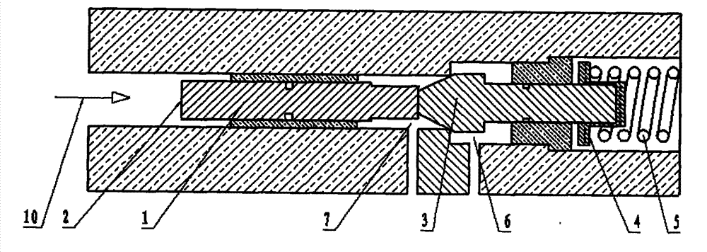
[0025] The operation mode of this embodiment is as follows: when the pressure on the cone valve tail 9 is lower than the preset pressure, the thrust of the spring 5 on the cone valve 3 is greater than the force exerted by the sensing pressure 10 on the cone valve 3 . The spring 5 transmits the thrust to the poppet valve 3 through the spring seat 4 and the valve core 1, forcing the poppet valve 3 to move toward the tail part 9 of the poppet valve, and the poppet valve 3 is pushed away. The oil in the inlet 6 enters the outlet 7 through this channel. As the sensing pressure 10 decreases, the opening speed of the poppet valve 3 will be faster until the pilot valve is fully opened to realize the opening of the pilot valve. When the sensing pressure 10 on the tail portion 9 of the cone valve is greater than the preset pressure, the pressure of the sensing pressure 10 on the cone valve 3 is greater than the thrust of the spring 5 on the cone valve 3 . The spring 5 is compressed, an...

Embodiment 3

[0027] All features disclosed in this specification, or steps in all methods or processes disclosed, may be combined in any manner, except for mutually exclusive features and / or steps.

[0028] Any feature disclosed in this specification (including any appended claims, abstract and drawings), unless expressly stated otherwise, may be replaced by alternative features which are equivalent or serve a similar purpose. That is, unless expressly stated otherwise, each feature is one example only of a series of equivalent or similar features.


PUM


Abstract

A high-low pressure pilot valve has a valve body provided with an inlet (6) and an outlet (7), a valve chamber is formed in the valve body, a valve core (1) is mounted in the valve chamber, two ends of the valve core (1) extend out of the valve chamber, wherein one end is a pressure detecting end and the other end is provided with an elastic return element; the valve chamber comprises a first chamber body and a second chamber body adjacent to the first chamber body, which communicate with the inlet (6) and the outlet (7), respectively, and a sealing surface is formed on a common boundary of the two chamber bodies; one section on the valve core (1) is a conical valve (3), a conical surface of the conical valve (3) is matched with the sealing surface to achieve sealing. The high-low pressure pilot valve has higher sensitivity, better responsibility and better reliability.

Description

technical field [0001] The invention relates to a valve in the oil and gas wellhead safety production, in particular to a high and low pressure pilot valve with an improved pilot valve therein. Background technique [0002] The control methods of surface safety valves and underwater safety valves widely used in oil and gas wellheads mainly include: pneumatic control, hydraulic control, and combined gas-hydraulic control. The core component of all control systems is the sensing pilot valve (Pilot). Since the piston valve body is not suitable for high-pressure applications in oil and gas wellheads, and its cylindrical spool has high requirements for the verticality of the two sealing surfaces, the deviation of the spool It will lead to sealing failure. At present, the sliding valve structure is generally adopted at home and abroad, such as figure 1 and figure 2 As shown, the spool of the pilot valve is installed in the through hole in the valve body. One end of the spool is...

Claims


Application Information

Patent Timeline
Patent Type & Authority Patents(China)
IPC IPC(8): F16K1/00F16K27/02F16K1/32F16K31/12
CPCF16K31/122
Inventor 梅宗斌
Owner SICHUAN HUAYU PETROLEUM DRILLING & PRODION EQUIP
Why Eureka
Try Eureka